Table of Contents
Advertisement
Quick Links
USER GUIDE AND SPECIFICATIONS
NI 9683
General Purpose Inverter Controller RIO Mezzanine Card
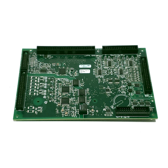
This document provides pinouts, connectivity information, and specifications for the National
Instruments 9683 General Purpose Inverter Control (GPIC) RIO Mezzanine Card (RMC).
Caution
compatibility (EMC), or CE marking compliance claims for the NI 9683. The
end-product supplier is responsible for conformity to any and all compliance
requirements.
Caution
Hazardous voltages may be present.
Caution
cooling may be necessary to keep the device under the maximum ambient
temperature rating for the NI 9683. Refer to the
information about the maximum ambient temperature rating.
Caution
signals connected to the NI 9683 are isolated and no unsafe voltages are present at
the NI 9683 inputs. Voltages that exceed the specifications could result in damage to
the NI 9683.
Caution
not electrically or mechanically compatible with other NI sbRIO devices.
Caution
Product misuse can result in a hazard. You can compromise the safety protection built
into the product if the product is damaged in any way. If the product is damaged,
return it to National Instruments for repair.
National Instruments makes no product safety, electromagnetic
The NI 9683 must be installed inside a suitable enclosure prior to use.
Exercise caution when placing the NI 9683 inside an enclosure. Auxiliary
The NI 9683 is designed for low voltage signals. You must ensure that all
Use the NI 9683 with only NI sbRIO-9605/9606 devices. The NI 9683 is
Do not operate the NI 9683 in a manner not specified in this user guide.
Specifications
section for more
Advertisement
Table of Contents

Subscribe to Our Youtube Channel
Related Manuals for National Instruments NI 9683


Summary of Contents for National Instruments NI 9683
- Page 1 The NI 9683 is designed for low voltage signals. You must ensure that all Caution signals connected to the NI 9683 are isolated and no unsafe voltages are present at the NI 9683 inputs. Voltages that exceed the specifications could result in damage to the NI 9683.
- Page 2 Scanned AI and AO LVTTL DIO Half-bridge DO sbRIO Mezzanine Connector Dimensions Figures 2 through 4 show dimensional drawings of the NI 9683. Figure 2. NI 9683 Primary Side Dimensions in Millimeters (Inches) 114.3 (4.500) 111.1 (4.374) 109.22 (4.300) 93.32 (3.674) 91.67 (3.609)
- Page 3 Figure 4. NI 9683 Maximum Height of Components in Millimeters (Inches) 9.98 (0.393) For more information about the dimensions of the NI 9683, including Note two-dimensional drawings and three-dimensional models, go to ni.com/ dimensions NI 9683 User Guide and Specifications | © National Instruments | 3...
- Page 4 Figure 5. Typical NI 9683 System Enclosure. The NI 9683 must be installed inside a suitable enclosure. NI sbRIO-9605/9606. Use the NI 9683 with only NI sbRIO-9605/9606 sbRIO devices. NI 9683. Interface board. The NI 9683 specifications assume direct board-to-board connections. Refer the...
- Page 5 Mating the NI 9683 to the NI sbRIO-9605/9606 Figure 6 shows how to mate the NI 9683 to the NI sbRIO-9605/9606. Ensure that the NI sbRIO-9605/9606 is powered off before connecting the NI 9683. You must use the standoffs specified below when mating the NI 9683 to...
- Page 6 24 sinking digital output channels, 4 relay control digital output channels, and 32 LVTTL digital input/output channels. Table 7 lists and describes the connectors on the NI 9683 and the part number and manufacturer of each connector. Refer to the manufacturer for information about using and matching these connectors.
- Page 7 DI P0.8 Control DI P0.7 DI P0.6 Sinking DO DI P0.5 DI P0.4 DO10 DI P0.3 DI P0.2 DO11 DI P0.1 DI P0.0 DO12 VI P0 Vext DO13 NI 9683 User Guide and Specifications | © National Instruments | 7...
- Page 8 – Simultaneous AI– NI 9683 NI 9683 Circuitry The NI 9683 analog channels share a common ground that is isolated from other parts of the board. The NI 9683 protects each channel from overvoltages. Refer to the Specifications section for more information about overvoltage protection. The incoming analog signal on each channel is buffered and conditioned by the differential amplifier and then sampled by a 12-bit ADC.
- Page 9 Then have a single connection from the plane to the CS COM pin of the NI 9683. The NI 9683 simultaneous analog inputs have ±10 V and ±5 V input ranges that can accommodate termination resistor values in a certain range, based on the sensor peak current.
- Page 10 Use signal sources with an output impedance of less than 2 kΩ to ensure specified performance. Large source impedances add to the input resistor inside the NI 9683, which results in increased settling time and decreases the accuracy of the measurement. Increased input impedance also results in a decrease of the -3 dB bandwidth.
-
Page 11: Sinking Digital Output
Sinking DO NI 9683 The NI 9683 has current sinking digital outputs, meaning that the output pin is driven to ground (GND) when the channel is ON. Make sure the devices you connect to the NI 9683 are compatible with the output specifications. - Page 12 The NI 9683 provides connections for four relay control digital output channels. Each channel has a relay control DO+ and a current return pin, relay control DO-. The NI 9683 has current sinking outputs, meaning the relay control DO+ is driven to relay control DO- when the channel is ON.
-
Page 13: Sourcing Digital Input
VI P0 and VI P1. This allows you to connect the DI to multivoltage systems. The NI 9683 has sourcing inputs, meaning the DI sources current from the VI P0 or VI P1 to the sinking output device.The NI 9683 internally limits current signals connected to DI. - Page 14 Supply NI 9683 The NI 9683 channel registers ON when the sinking-output is in the ON range. The channel registers as OFF when the sinking-output is in the OFF range. If no device is connected to the sourcing DI, the channel registers as OFF. Refer to the...
-
Page 15: System Diagrams
System Diagrams Figures 20 and 21 show diagrams for interfacing digital and analog signals with the NI 9683. Figure 20. Interfacing Digital Signals with the NI 9683 +24V Relay + Relay – Relay Control DO+ Relay Control DO– +24V_COM VI P0 (5 V to 24 V) - Page 16 Do not connect the AI- pin when using termination resistors. Use a small plane shape for the current return point to reduce the common-mode impedance. Do not connect CS COM to GND. 16 | ni.com | NI 9683 User Guide and Specifications...
-
Page 17: Specifications
-3 dB bandwidth ..........210 kHz CMRR (f = 60 Hz).......... 60 dB min Input impedance Differential..........240 kΩ Single-ended ..........120 kΩ Overvoltage protection ........±30 V max NI 9683 User Guide and Specifications | © National Instruments | 17... - Page 18 Startup voltage ..........0 V Ω With signal source impedance <2 k . Refer to the Scanned Analog Input (Monitoring) section for more information about the influence of source impedance over accuracy. 18 | ni.com | NI 9683 User Guide and Specifications...
- Page 19 High-range mode ........10 V to 24 V Not supported ........... 6 V to 10 V Digital logic levels Low-range mode OFF state........... ≥1.8 V min ON state ..........≤1 V max NI 9683 User Guide and Specifications | © National Instruments | 19...
- Page 20 )..5 V to 30 V Hold time is the amount of time input signals must be stable after initiating a read from the NI 9683. Setup time is the amount of time input signals must be stable before reading from the NI 9683.
- Page 21 = 30 V, CL = 50 pF......500 kHz The maximum switching frequency must be limited to 500 kHz, regardless of the supply voltage or the capacitive load, in order to prevent output driver overstress. NI 9683 User Guide and Specifications | © National Instruments | 21...
- Page 22 Maximum Switching Frequency (ktHz) Propagation delay = 5 V, CL = 50 pF ......300 ns max > 15 V, CL = 50 pF ......100 ns max Protection Overcurrent ..........None Short-circuit ..........None 22 | ni.com | NI 9683 User Guide and Specifications...
- Page 23 Turn ON rate is the minimum time between inrush current events and is based on the maximum inrush current over the maximum inrush time. You can turn OFF the relay control DO at any point during operation. NI 9683 User Guide and Specifications | © National Instruments | 23...
-
Page 24: Power Requirements
-to-GND..........0 VDC to 30 VDC LVTTL digital input/output ......0 VDC to 3.465 VDC Isolation Voltages Simultaneous analog input Channel-to-channel ........None Channel-to-common Continuous ........60 VDC, Measurement Category I Withstand ..........1,000 V 24 | ni.com | NI 9683 User Guide and Specifications... -
Page 25: Physical Characteristics
Such voltage measurements include signal levels, special equipment, limited-energy parts of equipment, circuits powered by regulated low-voltage sources, and electronics. Do not connect the NI 9683 to signals or use for measurements within Caution Measurement Categories II, III, or IV. -
Page 26: Waste Electrical And Electronic Equipment (Weee)
Where to Go for Support The National Instruments Web site is your complete resource for technical support. At ni.com/support you have access to everything from troubleshooting and application development self-help resources to email and phone assistance from NI Application Engineers. - Page 27 NI product. Refer to the Export Compliance Information at ni.com/legal/export-compliance for the National Instruments global trade compliance policy and how to obtain relevant HTS codes, ECCNs, and other import/export data. © 2012–2013 National Instruments. All rights reserved.
Need help?
Do you have a question about the NI 9683 and is the answer not in the manual?
Questions and answers