Danfoss VLT AutomationDrive FC 300 Operating Instructions Manual
90 kw–315 kw d-frame
Hide thumbs
Also See for VLT AutomationDrive FC 300:
- Design manual (296 pages) ,
- Programming manual (277 pages) ,
- Operating instructions manual (169 pages)

Related Manuals for Danfoss VLT AutomationDrive FC 300


Summary of Contents for Danfoss VLT AutomationDrive FC 300
- Page 1 MAKING MODERN LIVING POSSIBLE Operating Instructions, 90 kW–315 kW D-frame VLT® AutomationDrive FC 300...
- Page 2 The amount of wait time is listed in the Discharge Time table. Failure to wait the specified time after power has been removed before doing service or repair could result in death or serious injury. ® MG34U202 - VLT is a registered Danfoss trademark...
- Page 3 ® Automation Drive D-Frame Safety Operating Instructions ® MG34U202 - VLT is a registered Danfoss trademark...
-
Page 4: Table Of Contents
2.5.3 Earthing (Grounding) of Screened Control Cables 2.5.4 Control Terminal Types 2.5.5 Wiring to Control Terminals 2.5.6 Control Terminal Functions 2.6 Serial Communication 2.7 Optional Equipment 2.7.1 Load Share Terminals 2.7.2 Regeneration Terminals ® MG34U202 - VLT is a registered Danfoss trademark... - Page 5 5.4 International/North American Default Parameter Settings 5.5 Parameter Menu Structure 5.6 Remote Programming with MCT 10 Set-up Software 6 Application Examples 6.1 Introduction 6.2 Application Examples 7 Status Messages 7.1 Status Display ® MG34U202 - VLT is a registered Danfoss trademark...
- Page 6 9.1 Start Up and Operation 10 Specifications 10.1 Power-dependent Specifications 10.2 General Technical Data 10.3 Fuse Tables 10.3.1 Protection 10.3.2 Fuse Selection 10.3.3 Short Circuit Current Rating (SCCR) 10.3.4 Connection Tightening Torques Index ® MG34U202 - VLT is a registered Danfoss trademark...
-
Page 7: Introduction
If a frequency converter is ordered with one of the 2.4.3.2 Terminal Locations: D5h-D8h. following options, it is supplied with an options cabinet that makes it taller. • Brake chopper • Mains disconnect ® MG34U202 - VLT is a registered Danfoss trademark... -
Page 8: Purpose Of The Manual
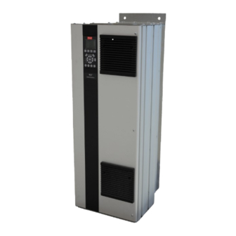
The remaining chapters provide supplementary details. These details include user interface, detailed programming, application examples, start-up trouble- shooting, and specifications. Illustration 1.3 D7h Enclosure ® MG34U202 - VLT is a registered Danfoss trademark... -
Page 9: Additional Resources
DC current specific requirements. Contact the local Danfoss • DC reactors Filter the intermediate DC supplier or visit the Danfoss website: http:// circuit voltage www.danfoss.com/BusinessAreas/DrivesSolutions/ • Documentations/Technical+Documentation.htm, for Prove line transient protection downloads or additional information. -
Page 10: Frame Sizes And Power Ratings
Normal Overload 400 V 500 V 525 V 690 V Table 1.4 kW Rated Frequency Converters HP High Overload HP Normal Overload 460 V 575 V Table 1.5 HP Rated Frequency Converters ® MG34U202 - VLT is a registered Danfoss trademark... -
Page 11: Installation
90% of the heat out of the Voltage [V] Altitude restrictions back channel of the frequency converters. The back- 380-500 At altitudes above 3 km, contact Danfoss regarding channel air can be redirected from the panel or room PELV using one of the kits below. -
Page 12: Lifting
IP54 (NEMA 12) Units Consider the following before selecting the final instal- lation site: • Free space for cooling • Access to open the door • Cable entry from the bottom ® MG34U202 - VLT is a registered Danfoss trademark... -
Page 13: Electrical Installation
Failure to isolate power, motor and control wiring could result in less than optimum frequency converter and associated equipment performance. ® MG34U202 - VLT is a registered Danfoss trademark... - Page 14 32 (D IN) (N RS-485) 69 0V (PNP) 24V (NPN) (COM RS-485) 61 33 (D IN) 0V (PNP) (PNP) = Source (NPN) = Sink 37 (D IN) Illustration 2.2 Interconnect Diagram ® MG34U202 - VLT is a registered Danfoss trademark...
- Page 15 Illustration 2.3 Example of Proper Electrical Installation Using Illustration 2.4. If not factory supplied, fuses must Conduit be provided by the installer as part of installation. See maximum fuse ratings in 10.3.1 Protection. ® MG34U202 - VLT is a registered Danfoss trademark...
-
Page 16: Earth (Grounding) Requirements
RFI filtering, screened motor cables, and • Danfoss recommends that all power connections frequency converter power. be made with a minimum 75 °C rated copper EN/IEC61800-5-1 (Power Drive System Product Standard) wire. -
Page 17: Earthing (Grounding) Ip20 Enclosures
• Connect the 3-phase motor wiring to terminals 96 (U), 97 (V), and 98 (W) • Earth (ground) the cable in accordance with the instructions provided ® MG34U202 - VLT is a registered Danfoss trademark... -
Page 18: Terminal Locations: D1H-D4H
WITH NUT Illustration 2.7 Terminal Locations D1h SECTION A-A MAINS TERMINALS SECTION B-B MOTOR TERMINALS AND BRAKE BRAKE TERMINALS BRAKE TERMINAL 11.5 MAINS TERMINAL MOTOR TERMINAL Illustration 2.8 Terminal Locations D3h ® MG34U202 - VLT is a registered Danfoss trademark... - Page 19 MOTOR TERMINALS AND MAINS TERMINALS BRAKE TERMINALS MAINS TERMINAL MOTOR TERMINAL 331.2 211.1 GROUND 168.4 168.4 GROUND GROUND 143.4 143.4 GROUND 4X M10x20 STUD WITH NUT Illustration 2.10 Terminal Locations D2h ® MG34U202 - VLT is a registered Danfoss trademark...
- Page 20 BRAKE / REGEN TERMINAL MAINS TERMINAL 14.8 12.6 MOTOR TERMINAL Illustration 2.11 Terminal Locations D4h [3.7] [4.9] [3.0] [7.5] Illustration 2.12 Load share and Regeneration Terminals, D4h Front view Side view Table 2.4 ® MG34U202 - VLT is a registered Danfoss trademark...
-
Page 21: Terminal Locations: D5H-D8H
MAINS TERMINAL BRAKE TERMINAL MAINS TERMINAL 28.6 24.5 20.4 GROUND 3X 511 20.1 MOTOR TERMINAL 3X M10X20 STUD WITH NUT 0 [ ] Illustration 2.14 Terminal Locations, D5h with Brake Option ® MG34U202 - VLT is a registered Danfoss trademark... - Page 22 MOTOR TERMINAL Illustration 2.15 Terminal Locations, D6h with Contactor Option SECTION A-A MAINS TERMINALS TB6 Terminal block for contactor MAINS TERMINAL Illustration 2.16 Terminal Locations, D6h with Contactor and Disconnect Options ® MG34U202 - VLT is a registered Danfoss trademark...
- Page 23 ® Automation Drive D-Frame Installation Operating Instructions SECTION A-A MAINS TERMINALS MAINS TERMINAL 18.4 Illustration 2.17 Terminal Locations, D6h with Circuit Breaker Option ® MG34U202 - VLT is a registered Danfoss trademark...
- Page 24 MOTOR TERMINAL MAINS TERMINAL 21.4 20.3 GROUND 412 16.2 15.6 BRAKE GROUND 3X 372 14.7 TERMINAL 4X M10X20 STUD WITH NUT 0 [ ] Illustration 2.18 Terminal Locations, D7h with Disconnect Option ® MG34U202 - VLT is a registered Danfoss trademark...
- Page 25 49.6 1202 47.3 1082 42.6 GROUND 2X 1034 MOTOR TERMINAL 40.7 GROUND 2X 1009 4X M10X20 STUD 39.7 WITH NUT 0 [ ] Illustration 2.19 Terminal Locations, D7h with Brake Option ® MG34U202 - VLT is a registered Danfoss trademark...
- Page 26 35.3 MOTOR TERMINAL BRAKE TERMINAL 4X M10X20 STUD 20.5 WITH NUT GROUND 418 16.5 15.8 GROUND 3X 378 14.9 0 [ ] Illustration 2.20 Terminal Locations, D8h with Contactor Option ® MG34U202 - VLT is a registered Danfoss trademark...
- Page 27 ® Automation Drive D-Frame Installation Operating Instructions SECTION C-C MAINS TERMINALS TB6 Terminal block for contactor MAINS TERMINAL 22.3 Illustration 2.21 Terminal Locations, D8h with Contactor and Disconnect Options ® MG34U202 - VLT is a registered Danfoss trademark...
- Page 28 ® Automation Drive D-Frame Installation Operating Instructions SECTION D-D MAINS TERMINALS MAINS TERMINAL 23.8 Illustration 2.22 Terminal Locations, D8h with Circuit Breaker Option ® MG34U202 - VLT is a registered Danfoss trademark...
-
Page 29: Motor Cable
(ground) capacity currents in accordance with IEC 61800-3. • Connect 3-phase AC input power wiring to terminals L1, L2, and L3 (see Illustration 2.23) ® MG34U202 - VLT is a registered Danfoss trademark... -
Page 30: Control Wiring Connection
Twisted copper wire or armoured steel wire cable Min. 16 mm Single-layer braided copper wire with varying Equalizing cable percentage screen coverage. This is the typical Danfoss reference cable. Table 2.8 Double-layer braided copper wire ® MG34U202 - VLT is a registered Danfoss trademark... -
Page 31: Control Terminal Types
Table 2.10 • Some options available for ordering with the unit may provide additional terminals. See the manual provided with the equipment option ® MG34U202 - VLT is a registered Danfoss trademark... -
Page 32: Wiring To Control Terminals
• The default terminal programming is intended to initiate frequency converter functioning in a typical operational mode Illustration 2.31 Location of Terminals 53 and 54 Switches and Bus Termination Switch ® MG34U202 - VLT is a registered Danfoss trademark... -
Page 33: Serial Communication
2.7.5 Mains Shield Illustration 2.32 shows both the covered and uncovered terminals. The mains shield is a Lexan cover installed inside the enclosure to provide protection according to VBG-4 accident-prevention requirements. ® MG34U202 - VLT is a registered Danfoss trademark... -
Page 34: Mains Disconnect
UL rating of the fequency converter and a short circuit current rating of 100,000 A. See 10.3 Fuse Tables for fuse recommendations. ® MG34U202 - VLT is a registered Danfoss trademark... -
Page 35: Start Up And Commissioning
• Vibration Check that the unit is mounted solidly or that shock mounts are used, as necessary • Check for an unusual amount of vibration Table 3.1 Start Up Check List ® MG34U202 - VLT is a registered Danfoss trademark... -
Page 36: Applying Power
LCP Custom Readout recommended are intended for start up and checkout purposes. Application settings may vary. See 4.1 Local Control Panel for detailed instructions on entering data through the LCP. Illustration 3.2 ® MG34U202 - VLT is a registered Danfoss trademark... -
Page 37: Local-Control Test
Increase the ramp-up time accel time in 3-41 Ramp 1 Ramp Up Time • Increase current limit in 4-18 Current Limit Illustration 3.5 • Increase torque limit in 4-16 Torque Limit Motor Mode ® MG34U202 - VLT is a registered Danfoss trademark... -
Page 38: System Start Up
Apply an external run command. Adjust the speed reference throughout the speed range. Remove the external run command. Note any problem. If warnings or alarms occur, see 8 Warnings and Alarms. ® MG34U202 - VLT is a registered Danfoss trademark... -
Page 39: User Interface
Navigation keys for programming functions, moving the display cursor, and speed control in local operation. Also included are the status indicator lights. Operational mode keys and reset. ® MG34U202 - VLT is a registered Danfoss trademark... -
Page 40: Setting Lcp Display Values
• For details about the frequency converter before it entered the alarm mode, select the alarm number using the navigation keys Auto Remote Running and press [OK]. Table 4.2 Illustration 4.3 ® MG34U202 - VLT is a registered Danfoss trademark... -
Page 41: Navigation Keys
LCP memory ALARM A fault condition causes the red alarm light to flash and an alarm text is displayed. Table 4.4 ® MG34U202 - VLT is a registered Danfoss trademark... -
Page 42: Uploading Data To The Lcp
Initialisation can be through 14-22 Operation Mode or manually. • Initialisation using 14-22 Operation Mode does not change frequency converter data such as operating hours, serial communication selections, ® MG34U202 - VLT is a registered Danfoss trademark... -
Page 43: Programming
Press [Quick Menu] and select the following parameters using the navigation keys to scroll to the titles and press 14.7% 0.00A 1(1) [OK] after each action. Analog Reference Q3-21 3-02 Minimum Reference 0.000 Hz Illustration 5.4 ® MG34U202 - VLT is a registered Danfoss trademark... - Page 44 Hz. (This tells the frequency converter that the minimum voltage received on terminal 53 (0 V) equals 20 Hz output). Illustration 5.10 Wiring Example for External Device Providing 0-10 V Control Signal ® MG34U202 - VLT is a registered Danfoss trademark...
-
Page 45: Control Terminal Programming Examples
Scroll to 5-10 Terminal 18 Digital Input. Press [OK] Value to access function choices. The default setting Start is shown. 6-50 Terminal 42 Speed 0-HighLim Speed 4-20 mA Output 14-20 Reset Mode Manual reset Infinite auto reset ® MG34U202 - VLT is a registered Danfoss trademark... -
Page 46: Parameter Menu Structure
• Press and hold [Main Menu] to enter a parameter number for direct access to that parameter • Details for common application set ups are provided in 6 Application Examples ® MG34U202 - VLT is a registered Danfoss trademark... - Page 47 ® Automation Drive D-Frame Programming Operating Instructions ® MG34U202 - VLT is a registered Danfoss trademark...
- Page 48 ® Automation Drive D-Frame Programming Operating Instructions ® MG34U202 - VLT is a registered Danfoss trademark...
- Page 49 ® Automation Drive D-Frame Programming Operating Instructions ® MG34U202 - VLT is a registered Danfoss trademark...
- Page 50 ® Automation Drive D-Frame Programming Operating Instructions ® MG34U202 - VLT is a registered Danfoss trademark...
-
Page 51: Remote Programming With Mct 10 Set-Up Software
Operating Instructions 5.6 Remote Programming with MCT 10 Set- up Software Danfoss has a software program available for developing, storing, and transferring frequency converter programming. The MCT 10 Set-up Software allows the user to connect a PC to the frequency converter and perform live programming rather than using the LCP. -
Page 52: Application Examples
+10 V A OUT A IN -10 - +10V A IN U - I A OUT Table 6.3 Analog Speed Reference (Voltage) Table 6.1 AMA with T27 Connected ® MG34U202 - VLT is a registered Danfoss trademark... - Page 53 [0] No operation, a jumper wire to terminal 27 is A IN not needed. A IN A OUT Latched Start (18) Stop Inverse (27) Illustration 6.2 Table 6.5 Start/Stop Command with Safe Stop ® MG34U202 - VLT is a registered Danfoss trademark...
- Page 54 D IN +10 V D IN A IN D IN A IN +10 V A OUT A IN A IN A OUT Table 6.8 External Alarm Reset Table 6.10 Speed Up/Down ® MG34U202 - VLT is a registered Danfoss trademark...
- Page 55 Select protocol, address and D IN baud rate in the above D IN mentioned parameters. D IN +10 V A IN A IN A OUT RS-485 Table 6.11 RS-485 Network Connection ® MG34U202 - VLT is a registered Danfoss trademark...
- Page 56 5 s then the frequency converter continues and the warning disappears. But Relay 1 will still be triggered until [Reset] on the LCP. Table 6.13 Using SLC to Set a Relay ® MG34U202 - VLT is a registered Danfoss trademark...
-
Page 57: Status Messages
2-12 Brake Power Limit (kW) is reached. • Coast Coast inverse was selected as a function for a digital input (parameter group 5-1* Digital Inputs). The corresponding terminal is not connected. • Coast activated by serial communication ® MG34U202 - VLT is a registered Danfoss trademark... - Page 58 Changing the reference is now only Ref. high The sum of all active references is above the possible via terminal functions speed up and reference limit set in 4-55 Warning Reference speed down. High. ® MG34U202 - VLT is a registered Danfoss trademark...
- Page 59 Once the cause of the alarm is cleared, power must be cycled to the frequency converter. The frequency converter can then be reset manually by pressing [Reset] or remotely by control terminals or serial communication. Table 7.3 Operation Status ® MG34U202 - VLT is a registered Danfoss trademark...
-
Page 60: Warnings And Alarms
A trip can be reset in any of 4 ways: Earth Fault [A14] Auto Remote Trip • Press [Reset] on the LCP Illustration 8.2 • Digital reset input command • Serial communication reset input command • Auto reset ® MG34U202 - VLT is a registered Danfoss trademark... - Page 61 In addition to the text and alarm code on the frequency converter LCP, there are three status indicator lights. Warn. Alarm Hand Auto Off Reset Illustration 8.3 Warning LED Alarm LED Warning Alarm On (Flashing) Trip-Lock On (Flashing) Table 8.1 ® MG34U202 - VLT is a registered Danfoss trademark...
-
Page 62: Warning And Alarm Definitions
Overload of Digital Output Terminal 27 5-00 Digital I/O Mode, 5-01 Terminal 27 Mode Overload of Digital Output Terminal 29 5-00 Digital I/O Mode, 5-02 Terminal 29 Mode Ovrld X30/6-7 Ext. Supply (option) ® MG34U202 - VLT is a registered Danfoss trademark... - Page 63 Analog input 54 wrong settings S202 Mixing Fan Fault 14-53 ATEX ETR cur.lim.warning ATEX ETR cur.lim.alarm ATEX ETR freq.lim.warning ATEX ETR freq.lim.alarm Brake IGBT Heatsink temp. Heatsink sensor Parameter group 0-7* ® MG34U202 - VLT is a registered Danfoss trademark...
-
Page 64: Fault Messages
Options are programmed at 14-12 Function at Mains 98% and trips at 100%, while giving an alarm. The Imbalance. frequency converter cannot be reset until the counter is Troubleshooting below 90%. ® MG34U202 - VLT is a registered Danfoss trademark... - Page 65 18 or 19 (digital input PNP only) Check for earth faults in the motor by measuring and terminal 50. the resistance to ground of the motor leads and the motor with a megohmmeter. ® MG34U202 - VLT is a registered Danfoss trademark...
- Page 66 Incorrect airflow clearance above and below the The fan warning function is an extra protective function frequency converter that checks if the fan is running/mounted. The fan warning can be disabled in 14-53 Fan Monitor ([0] Disabled). ® MG34U202 - VLT is a registered Danfoss trademark...
- Page 67 Check for loose or missing wiring 2304 Could not read any data from power EEPROM It may be necessary to contact your Danfoss supplier or 2305 Missing SW version from power unit service department. Note the code number for further...
-
Page 68: 48 1.8 V Supply Low
Control board hardware. 5125 Option in slot C0: Hardware incompatible with ALARM 50, AMA calibration failed control board hardware. Contact your Danfoss supplier or Danfoss Service 5126 Option in slot C1: Hardware incompatible with Department. control board hardware. ALARM 51, AMA check U... -
Page 69: Current Limit
One or more options have either been added or removed CSIV failed to init a parameter. since the last power-down. Check that the configuration ALARM 85, Dang fail PB: change is intentional and reset the unit. Profibus/Profisafe Error. ® MG34U202 - VLT is a registered Danfoss trademark... -
Page 70: 104 Mixing Fan Fault
Reset the frequency converter for normal operation. WARNING 251, New typecode The power card or other components have been replaced and the typecode changed. Reset to remove the warning and resume normal operation. ® MG34U202 - VLT is a registered Danfoss trademark... -
Page 71: Basic Troubleshooting
3-13 Reference Site. Set preset reference active? Terminal reference active in parameter connection correct? Scaling of group 3-1* References. Check for terminals correct? Reference signal correct wiring. Check scaling of available? terminals. Check reference signal. ® MG34U202 - VLT is a registered Danfoss trademark... -
Page 72: Parameter Group
Rotate output motor leads one If imbalance leg stays on same converters. position: U to V, V to W, W to U. output terminal, it is a problem with the unit. Contact the supplier. ® MG34U202 - VLT is a registered Danfoss trademark... - Page 73 Change switching pattern and acceptable limit. certain frequencies) frequency in parameter group 14-0* Inverter Switching. Increase Resonance Dampening in 1-64 Resonance Dampening. Table 9.1 ® MG34U202 - VLT is a registered Danfoss trademark...
-
Page 74: Specifications
0-590 Hz Heatsink overtemperature trip 110 °C Control card ambient trip 75 °C *High overload=150% current for 60 s, Normal overload=110% current for 60 s. Table 10.1 Mains Supply 3x380-500 V AC ® MG34U202 - VLT is a registered Danfoss trademark... - Page 75 0–590 Hz Heatsink overtemperature trip 110 °C Control card ambient trip 75 °C *High overload=150% current for 60 s, Normal overload=110% current for 60 s. Table 10.2 Mains Supply 3x525-690 V AC ® MG34U202 - VLT is a registered Danfoss trademark...
- Page 76 D1h ratings+disconnect and/or brake chopper 166 (255) D1h ratings+contactor and/or circuit breaker 129 (285) D2h ratings+disconnect and/or brake chopper 200 (440) D2h ratings+contactor and/or circuit breaker 225 (496) Table 10.4 D5h–D8h Weights ® MG34U202 - VLT is a registered Danfoss trademark...
-
Page 77: General Technical Data
1) Terminals 27 and 29 can also be programmed as output. Analog inputs Number of analog inputs Terminal number 53, 54 Modes Voltage or current Mode select Switches A53 and A54 ® MG34U202 - VLT is a registered Danfoss trademark... - Page 78 27, 29 Voltage level at digital/frequency output 0-24 V Max. output current (sink or source) 40 mA Max. load at frequency output 1 kΩ Max. capacitive load at frequency output 10 nF ® MG34U202 - VLT is a registered Danfoss trademark...
- Page 79 System response time (terminals 18, 19, 27, 29, 32, 33) Speed control range (open loop) 1:100 of synchronous speed 30-4000 rpm: Maximum error of ±8 rpm Speed accuracy (open loop) All control characteristics are based on a 4-pole asynchronous motor ® MG34U202 - VLT is a registered Danfoss trademark...
- Page 80 Monitoring of the intermediate circuit voltage ensures that the frequency converter trips if the intermediate circuit voltage is too low or too high. • The frequency converter is protected against earth (ground) faults on motor terminals U, V, W. ® MG34U202 - VLT is a registered Danfoss trademark...
-
Page 81: Fuse Tables
10.3.2 Fuse Selection gear, machines etc., must be short-circuited and over- current protected according to national/international Danfoss recommends using the following fuses which will regulations. ensure compliance with EN50178. In case of malfunction, not following the recommendation may result in Short-circuit Protection: unnecessary damage to the frequency converter. -
Page 82: Short Circuit Current Rating (Sccr)
Table 10.9 Frequency Converter Supplied with a Contactor With a Bussmann type LPJ-SP or Gould Shawmut type AJT fuse. 450 A max fuse size for D6h and 900 A max fuse size for D8h. ® MG34U202 - VLT is a registered Danfoss trademark... -
Page 83: Index
(Grounding)..................32 (Grounding) IP20 Enclosures............14 (Grounding) IP21/54 Enclosures..........14 (Grounding) Of Screened Control Cables....... 27 'Earthing (grounding) Hazard............13 Electrical Installation..................10 Noise..................... 13 EMC....................28, 32, 77 Equalizing Cable................... 27 ® MG34U202 - VLT is a registered Danfoss trademark... - Page 84 Installation Current................... 54, 62, 75 Installation............... 5, 12, 32, 33 Signal....................43 Site......................8 Overcurrent.................... 54 Isolated Mains..................26 Overload Protection................ 8, 12 Overvoltage..................34, 54 Leakage Current (>3.5 MA)............... 13 ® MG34U202 - VLT is a registered Danfoss trademark...
- Page 85 Screened Control Cables..............27 Wiring To Control Terminals............. 29 Serial Communication......... 6, 27, 28, 38, 54, 57, 30 Set Up....................... 37 Setpoint....................54 Set-up....................... 37 Shielded Cable....................10, 32 Wire....................... 12 ® MG34U202 - VLT is a registered Danfoss trademark...
- Page 86 130R0291 MG34U202 Rev. 2012-06-15 *MG34U202*...
Need help?
Do you have a question about the VLT AutomationDrive FC 300 and is the answer not in the manual?
Questions and answers