
Related Manuals for Clarke RANGER 6/500


Summary of Contents for Clarke RANGER 6/500
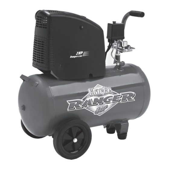
- Page 1 50L OIL FREE AIR COMPRESSOR MODEL NO: RANGER 6/500 PART NO: 2242015 OPERATION & MAINTENANCE INSTRUCTIONS ORIGINAL INSTRUCTIONS LS0620 - ISS 4...
-
Page 2: Parts And Servicing
INTRODUCTION Thank you for purchasing this CLARKE 50L Oil Free Air Compressor. Please read this manual fully before use and follow the instructions carefully. In doing so you will ensure the safety of yourself and those around you, and you can look forward to your purchase giving you long and satisfactory service. -
Page 3: Safety Precautions
SAFETY PRECAUTIONS Before using your compressor it is in your own interest to read and pay attention to the following safety rules. 1. Compressed air is dangerous. Do not point a jet of air at persons or animals, and do not discharge compressed air against the skin. -
Page 4: Safety Symbols
SAFETY SYMBOLS Read this instruction booklet carefully before positioning, operating or adjusting the compressor. Risk of electric shock. The compressor must be disconnected from the mains supply before removing any covers. Do not use in a damp environment. Risk of accidental start-up. The compressor could start automatically in the event of a power cut and subsequent reset. -
Page 5: Electrical Connections
ELECTRICAL CONNECTIONS WARNING! Read these electrical safety instructions thoroughly before connecting the product to the mains supply. Connect the mains lead to a standard, 230 Volt (50Hz) electrical supply through an approved 13 amp BS 1363 plug, or a suitably fused isolator switch. If the plug has to be changed because it is not suitable for your socket, or because of damage, it must be removed and a replacement fitted, following the wiring instructions shown below. -
Page 6: Attach The Wheels
ASSEMBLY ATTACH THE WHEELS Use a suitable spanner to attach the wheels to the compressor. Use the washers and spring washer in the positions shown. ATTACH THE SUPPORT FEET Insert the support feet into the position shown. FIT THE AIR FILTER 1. -
Page 7: Before Use
BEFORE USE Before connecting your compressor to the power supply, check the following:- • Set the ON/OFF switch to the OFF position (pushed down). • Make sure that the compressor is on level ground. • Make sure that the supply voltage matches the voltage shown on the data label. -
Page 8: Operation
OPERATION If the compressor has not been used for more then 24 hours, open the drain valve (on the bottom of the reservoir) and drain any condensate which has collected. See page 10. ATTACHING AIR TOOLS WARNING: BEFORE CONNECTING AIR TOOLS, MAKE SURE THAT YOU READ THE INSTRUCTIONS SUPPLIED WITH THE TOOL, ALSO ENSURE THAT THE TOOL IS SUITABLE FOR USE WITH THE COMPRESSOR AND HOSE SPECIFICATIONS. -
Page 9: Set The Output Pressure
SET THE OUTPUT PRESSURE When viewed from the front, the left hand outlet valve is adjustable. The right hand outlet valve will only supply the full reservoir pressure and is not adjustable. 1. Use the pressure regulator to set the output pressure of the left hand outlet valve. -
Page 10: Turning The Compressor Off
2. Turn the outlet valve handle to the off position. 3. Operate the tool to depressurise the air hose. 4. Disconnect the tool from the hose. TURNING THE COMPRESSOR OFF 1. Follow steps 1-3 in “Removing Tools From The Air Hose” above. 2. -
Page 11: Reset Button
RESET BUTTON This compressor has a thermal overload device. If the motor gets too hot, the thermal overload device cuts the power which prevents damage to the motor. If the thermal overload device operates, let the motor cool down for 5 minutes and push the reset button. -
Page 12: Maintenance
MAINTENANCE DRAIN THE RESERVOIR (DAILY) After use, always open the drain valve to make sure that any condensate is drained off. CLEAN THE AIR FILTER (MONTHLY) The air filter must be examined monthly, more often in dusty conditions, 1. Remove the filter from the compressor. -
Page 13: Check The Non-Return Valve (Every 6 Months)
CHECK THE NON-RETURN VALVE (EVERY 6 MONTHS) If the reservoir pressure decreases for no apparent reason, it is possible that the non-return valve is leaking. To check, 1. Make sure that the reservoir is not under pressure and the compressor is switched OFF and disconnected from the power supply. -
Page 14: Troubleshooting
1. Switch off and wait approx 5 tripped. minutes. 2. Press the reset button and switch on again. Motor windings burnt out. 1. Contact your Clarke dealer for a replacement motor. The compressor Compressor head gasket 1. Return the machine to your does not reach blown or valve broken. -
Page 15: Exploded Diagram
EXPLODED DIAGRAM Parts & Service: 020 8988 7400 / E-mail: Parts@clarkeinternational.com or Service@clarkeinternational.com... -
Page 16: Parts List
PARTS LIST NO DESCRIPTION NO DESCRIPTION Nut M3 Bolt M6×25 Capacitor Bolt M6×35 Tooth Washer Spring Washer 6 Screw St3.9x12 Cylinder Head Washer O Ring Discharge Pipe D10mm Valve Plate Subassembly Elbow Connecter Cylinder Seals Air Filter Cylinder 60 Fan Cover Connection Stud Big Washer 8 Screw M5×16... -
Page 17: Declaration Of Conformity
DECLARATION OF CONFORMITY Parts & Service: 020 8988 7400 / E-mail: Parts@clarkeinternational.com or Service@clarkeinternational.com... - Page 18 DECLARATION OF CONFORMITY Parts & Service: 020 8988 7400 / E-mail: Parts@clarkeinternational.com or Service@clarkeinternational.com...
-
Page 19: Popular Accessories
POPULAR ACCESSORIES Parts & Service: 020 8988 7400 / E-mail: Parts@clarkeinternational.com or Service@clarkeinternational.com...
Need help?
Do you have a question about the RANGER 6/500 and is the answer not in the manual?
Questions and answers