
Subscribe to Our Youtube Channel
Related Manuals for Clarke RANGER 6/240


Summary of Contents for Clarke RANGER 6/240
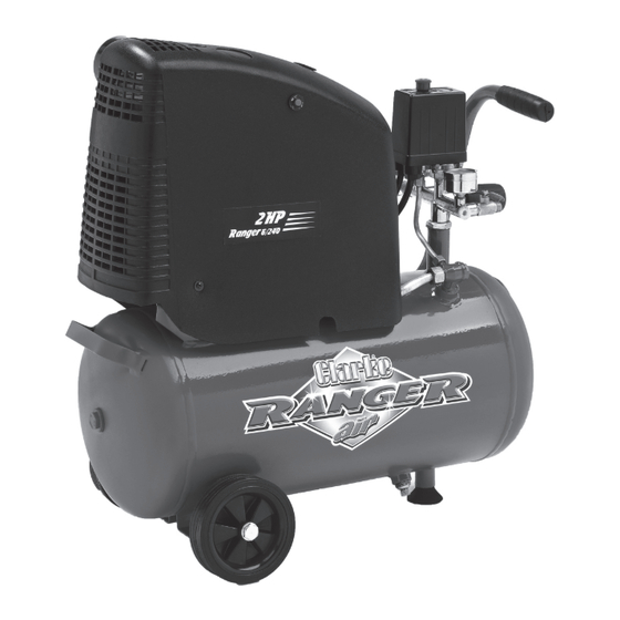
- Page 1 24L OIL FREE AIR COMPRESSOR MODEL NO: RANGER 6/240 PART NO: 2242010 OPERATION & MAINTENANCE INSTRUCTIONS LS1212...
-
Page 2: Parts And Servicing
INTRODUCTION Thank you for purchasing this CLARKE 24L Oil Free Air Compressor. Please read this manual fully before use and follow the instructions carefully. In doing so you will ensure the safety of yourself and those around you, and you can look forward to your purchase giving you long and satisfactory service. -
Page 3: Safety Precautions
2. DO NOT operate your compressor with the guard removed. 3. Repairs must only be carried out by a qualified engineer. If problems occur, contact your Clarke dealer. 4. Before carrying out any maintenance, make sure that the pressure is released from the air reservoir, and that the compressor is disconnected from the electrical supply. -
Page 4: Electrical Connections
ELECTRICAL CONNECTIONS WARNING! Read these electrical safety instructions thoroughly before connecting the product to the mains supply. Connect the mains lead to a standard, 230 Volt (50Hz) electrical supply through an approved 13 amp BS 1363 plug, or a suitably fused isolator switch. If the plug has to be changed because it is not suitable for your socket, or because of damage, it must be removed and a replacement fitted, following the wiring instructions shown below. -
Page 5: Attach The Wheels
ASSEMBLY ATTACH THE WHEELS Use a suitable spanner to attach the wheels to the compressor. Use the washers and spring washer in the positions shown. ATTACH THE SUPPORT FOOT Insert the support foot into the position shown. FIT THE AIR FILTER 1. -
Page 6: Before Use
BEFORE USE Before connecting your compressor to the power supply, check the following:- • Set the ON/OFF switch to the OFF position (pushed down). • Make sure that the compressor is on level ground. • Make sure that the supply voltage matches the voltage shown on the data label. -
Page 7: Operation
OPERATION If the compressor has not been used for more then 24 hours, open the drain valve (on the bottom of the reservoir) and drain any condensate which has collected. See page 10. ATTACHING AIR TOOLS WARNING: BEFORE CONNECTING AIR TOOLS, MAKE SURE THAT YOU READ THE INSTRUCTIONS SUPPLIED WITH THE TOOL, ALSO ENSURE THAT THE TOOL IS SUITABLE FOR USE WITH THE COMPRESSOR AND HOSE SPECIFICATIONS. -
Page 8: Check The Safety Valve
CHECK THE SAFETY VALVE To make sure that the safety valve works correctly. 1. Pull on the ring attached. • Air will be released when you pull on the ring and stop when released. 2. If the valve does not operate in this way, do not use the compressor. -
Page 9: Removing Tools From The Air Hose
REMOVING TOOLS FROM THE AIR HOSE WARNING: ALWAYS SET THE PRESSURE REGULATOR TO ZERO BEFORE YOU REMOVE OR REPLACE A TOOL. 1. Push down on the On/Off button to stop the compressor. 2. Turn the outlet valve handle to the off position. -
Page 10: Draining The Reservoir
DRAINING THE RESERVOIR CAUTION: YOU MUST DRAIN THE RESERVOIR AFTER EACH DAYS USE AND BEFORE YOU PUT YOUR COMPRESSOR INTO STORAGE. 1. Turn the compressor off and disconnect from the power supply. 2. Put a container below the drain valve to collect the condensate. 3. -
Page 11: Maintenance
MAINTENANCE DRAIN THE RESERVOIR (DAILY) After use, always open the drain valve to make sure that any condensate is drained off. CLEAN THE AIR FILTER (MONTHLY) The air filter must be examined monthly, more often in dusty conditions, 1. Remove the filter from the compressor. -
Page 12: Check The Non-Return Valve (Every 6 Months)
CHECK THE NON-RETURN VALVE (EVERY 6 MONTHS) If the reservoir pressure decreases for no apparent reason, it is possible that the non-return valve is leaking. To check, 1. Make sure that the reservoir is not under pressure and the compressor is switched OFF and disconnected from the power supply. -
Page 13: Troubleshooting
1. Switch off and wait approx 5 tripped. minutes. 2. Press the reset button and switch on again. Motor windings burnt out. 1. Contact your Clarke dealer for a replacement motor. The compressor Compressor head gasket 1. Return the machine to your does not reach blown or valve broken. -
Page 14: Exploded Diagram
EXPLODED DIAGRAM Parts & Service: 020 8988 7400 / E-mail: Parts@clarkeinternational.com or Service@clarkeinternational.com... -
Page 15: Parts List
PARTS LIST Description Part No Description Part No Description Part No Bolt M6×25 HTRAN624001 Spring Washer HTRAN624035 Pressure Switch HTRAN624070 Bolt M6×35 HTRAN624002 Tooth Washer 4 HTRAN624036 Release Pipe HTRAN624071 Spring Washer HTRAN624003 Screw M3×6 HTRAN624037 Cylinder Head HTRAN624004 Spring Washer HTRAN624038 O Circle HTRAN624005... -
Page 16: Declaration Of Conformity
DECLARATION OF CONFORMITY Parts & Service: 020 8988 7400 / E-mail: Parts@clarkeinternational.com or Service@clarkeinternational.com... - Page 17 DECLARATION OF CONFORMITY Parts & Service: 020 8988 7400 / E-mail: Parts@clarkeinternational.com or Service@clarkeinternational.com...
-
Page 18: Popular Accessories
POPULAR ACCESSORIES Parts & Service: 020 8988 7400 / E-mail: Parts@clarkeinternational.com or Service@clarkeinternational.com... - Page 19 NOTES Parts & Service: 020 8988 7400 / E-mail: Parts@clarkeinternational.com or Service@clarkeinternational.com...
Need help?
Do you have a question about the RANGER 6/240 and is the answer not in the manual?
Questions and answers