
Related Manuals for Parker MT-700 Series


Summary of Contents for Parker MT-700 Series
- Page 1 Supermarket Control Solutions Installation and Operation Manual PUID 70-MTA-1017 R4.0 11221...
- Page 2 OFFER OF SALE The items described in this document are hereby offered for sale by Parker Hannifin Corporation, its subsidiaries or its authorized distributors. This offer and its acceptance are governed by the provisions stated in the detailed “Offer of Sale” elsewhere in this document or available at www.parker.com.
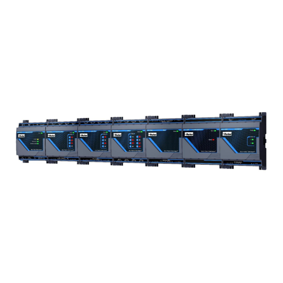
- Page 3 If the MT-722A is loaded with a battery cell or if any relay of a of MT-700 module is used to control voltage higher than 24V the entire row should be housed in an electrical enclosure. MT-700 series installer guide Page 3...
- Page 4 U700 Passive or powered Fuse sensors Passive or powered Fuse sensors (Building Passive or Automated powered Fuse Station) sensors Passive or powered sensors Data Add as much U700 cable as power permit MT-700 series installer guide Page 4...
- Page 5 For all other sensor types, refer to the instructions supplied with the sensor for proper wiring. The USB port are for service purposes only and must not be used to power appliances. 4A Fuse WARNING!: Remove power before adding or removing expansion module to avoid dammage MT-700 series installer guide Page 5...
-
Page 6: Basic Setup
3) Leave all other defaults, and press ‘OK’. NOTE: The sensor’s icon can be moved to a different position on the current view. While holding the CTRL key, click-and-drag the icon to the desired location. MT-700 series installer guide Page 6... -
Page 7: Basic Operation
The Lon Rx/Tx LED shows activity on the LonWorks® network. The RS485 Rx/Tx and Ethernet Act/Lnk LEDs are not used on U700 Monitoring Node. MT-700 series installer guide Page 7... -
Page 8: Changing Settings
Many settings for sensors can be changed at any time, should the need arise. However, there are a few exceptions: 1) The (hardware) Model cannot be changed on a Node after it has been dropped in Alliance. To change hardware type, the node must be deleted and a new node dropped. MT-700 series installer guide Page 8... -
Page 9: Additional Features
However, if a sensor never requires an alarm (e.g., an auxiliary input), it may be preferable to leave the alarm enabled with the alarm limits set to the sensor’s min/max range. This will effectively disable the alarm, but will not affect the Alliance display. MT-700 series installer guide Page 9... -
Page 10: Remote Sensors
NOTE: Remote sensors utilize the same resources on the Sensor Node as a physical sensor. Therefore, a remote sensor requires an open input on the controller; and a physical sensor cannot be assigned to an input already assigned to a remote sensor. MT-700 series installer guide Page 10... - Page 11 NAND, OR, NOR, XOR, XNOR. NOTE: Calculations can only be performed on inputs of the same data type. MT Alliance™ enforces this rule, and will only allow the user to select inputs that match the specified data type. MT-700 series installer guide Page 11...
-
Page 12: Operating Temperature
8.90 x 5.97 x 2.20 inches 226 x 152 x 56 mm Compliance: UL/CUL Listed Manufactured by: Parker Hannifin Canada 12855 rue Brault Mirabel, Qc, Canada J7J 0C4 Micro Thermo Technologies is a trademark of Parker Hannifin Canada MT-700 series installer guide Page 12... - Page 13 U700 Field Wiring 4A Fuse MT-700 series installer guide Page 13...
-
Page 14: System Specification
Can be a USB host or a USB device USB "OTG" port Full Speed. USB 2.0 Full Speed. USB 2.0 USB "Device" port MSD (mass storage device) profile currently supported *The USB port are for service purposes only MT-700 series installer guide Page 14... - Page 15 Do not (recharge), disassemble, heat above 100°C (212°F) or incinerate. Replace cell with Panasonic or Energizer CR1220 model only. Use of another cell may present a risk of fire or explosion. 22 NO 2022 MT-700 series installer guide Page 15...
- Page 16 100 mA max. (internally limited) Indicators / Buttons: Status Green LED Status Red LED Hardware features: Microcontroller ARM Cortex-M0, 48MHz 64Kbytes of flash memory for program 8K of SRAM for data 26 MR 2014 MT-700 series installer guide Page 16...
- Page 17 Status of relays (RO) 1 to 4 Relay test button (x4) To manually activate relays (RO) 1 to 4 Hardware features: Microcontroller ARM Cortex-M0, 48MHz 64Kbytes of flash memory for program 8K of SRAM for data 20 FE 2018 MT-700 series installer guide Page 17...
- Page 18 Status Green LED Status Red LED Valve 1 status LED Valve 2 status LED Hardware features: Microcontroller ARM Cortex-M0, 48MHz 64Kbytes of flash memory for program 8K of SRAM for data 26 MR 2014 MT-700 series installer guide Page 18...
- Page 19 Status of relays (RO) 1 to 4 Relay test button (x4) To manually activate relays (RO) 1 to 4 Hardware features: Microcontroller ARM Cortex-M0, 48MHz 64Kbytes of flash memory for program 8K of SRAM for data 20 FE 2018 MT-700 series installer guide Page 19...
- Page 20 Status Red LED Valve status LED (x8) Status of MVC outputs 1 to 8 Hardware features: Microcontroller ARM Cortex-M0, 48MHz 64Kbytes of flash memory for program 8K of SRAM for data 12 MA 2015 MT-700 series installer guide Page 20...
- Page 21 2AG / 5A / 250V / Slow or fast acting Life 100K cycles at 5A 250VAC resistive load on NO. 30K cycles at 5A 250VAC resistive load on NO or NC. Pilot duty 30VDC 1A on NO or NC. 20 FE 2018 MT-700 series installer guide Page 21...
-
Page 22: Analog Outputs (Ao)
(0 to 90% in current mode) Minimum pulse width 0V-10V-0V coming... 26 MR 2014 Temperature range (for all MT-700 modules) Operating -25°C to 60°C, 90% RH non-condensing Storage -25°C to 70°C, 90% RH non-condensing 14 JL 2014 MT-700 series installer guide Page 22...
Need help?
Do you have a question about the MT-700 Series and is the answer not in the manual?
Questions and answers