Table of Contents
Advertisement
Advertisement
Table of Contents

Related Manuals for Parker IOTA ONE Series


Summary of Contents for Parker IOTA ONE Series
- Page 1 IOTA ONE SHEET 1 OF 20...
- Page 2 SAFETY PRECAUTIONS MANUAL – Before attempting to install or operate the unit, read and familiarize yourself with all of the safety, installation, and operational instructions in this manual. This manual contains valuable safety, operational, and troubleshooting information and should be maintained for future reference. WARNINGS –...
-
Page 3: Table Of Contents
TABLE OF CONTENTS Table of Contents Section 1 General Information 1.1 Scope 1.2 Purpose of equipment 1.3 Description of instrument 1.4 Specifications 1.5 Equipment supplied 1.6 Accessories required but not supplied 1.7 Optional test equipment Section 2 Installation 2.1 Unpacking 2.2 Installation 2.3 Driver Settings 2.4 Connections... -
Page 4: Section 1 General Information
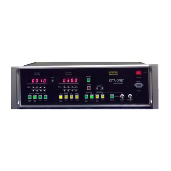
This manual describes the operation of the IOTA ONE valve driver instrument, Parker part number 060-0010-900. This instrument is similar in operation and performance to the Parker part number 060-0001-900 instrument, but with electronic displays, increased timing accuracy, and remote operation capability. - Page 5 Timing Error LED Off Indicator LED Power Switch/ On Indicator LED Pilot Light Memory Save/Recall On Time Range Off Time Range Mode Select Valve Jack Off Time On Time Adjustments External Trigger Remote Input Adjustments and Indicator Figure 1.1 View of Front Panel Showing Controls, Indicators, and Connectors “ON-TIME”...
- Page 6 the display permit the user to increment and decrement the value of each digit. Note that the display automatically carries over to the next digit(s) when incrementing past 9 and decrementing past 0. RANGE – Four-position momentary switch/indicators determine the time range (milliseconds, seconds, or minutes) or selects frequency mode for the “OFF-TIME DURATION”...
-
Page 7: Specifications
SAVE -- This momentary push button saves the current settings of the instrument to non-volatile memory. Upon power up, the instrument loads the most recent SAVE settings. RECALL – This momentary push button restores the most recent SAVE settings to the instrument. ®... -
Page 8: Accessories Required But Not Supplied
1.6 ACCESSORIES REQUIRED BUT NOT SUPPLIED ® To operate the IOTA ONE instrument, a Parker valve must be ordered separately. No additional equipment is required. In the event of abnormal operation, the instrument should be put into the hands of a qualified technician to troubleshoot the problem. -
Page 9: Section 2 Installation
SECTION 2 INSTALLATION 2.1 UNPACKING ® Before unpacking the IOTA ONE , examine the packing container and notify the shipping carrier of any damage. Unpack the contents of the container carefully and take inventory of the contents. Save the container and the packing material in the event that the instrument needs to be returned to the factory for servicing. - Page 10 2.3.3 The instrument is factory set for a burst pulse length of 180 microseconds. To change the burst pulse length, find the 8-position DIP switch as designated on Figure 2.1. The base (minimum) length is 50 microseconds. Setting one or more of the DIP switches OFF adds to this base time setting.
-
Page 11: Connections
high voltage pulse to operate correctly. Ideally, the setting should be as short as possible while still yielding consistent results. The maximum setting should not exceed 320 microseconds. 2.3.4 The holding voltage for the valve is also set on the driver PC board with a 4-position jumper as depicted in Figure 2.1. - Page 12 If the power indicator still fails to illuminate, place the instrument into the hands of a qualified technician to troubleshoot the problem. 2.5.2 Referring to section 1.3 as required, set the instrument to the following state: ON TIME 0040 Milliseconds OFF TIME 040.0 Milliseconds MODE...
-
Page 13: Section 3 Operation
SECTION 3 OPERATION 3.1 FRONT PANEL CONTROLS AND INDICATORS ® The front panel controls, indicators, and connectors of the IOTA ONE described in section 1.3 and are depicted in Figure 1.1. 3.2 OPERATING MODES ® The IOTA ONE Pulse Driver unit has four operating modes selected by depressing one of the four buttons below the START and STOP buttons just right of center on the front panel. -
Page 14: External One Shot
3.2.3 EXTERNAL ONE SHOT – When the EXT INPUT TTL is high or the SIGNAL button is depressed, the OFF TIMER will be triggered. When the OFF TIMER times out, the ON TIMER will be triggered. If the OFF TIMER is set to 000.0 or if FREQ mode is selected, there will be no delay between the trigger and the ON TIMER trigger. - Page 15 Figure 3.1 Screen shot of GUI Application for Remote Operation The fields in the GUI labeled ON TIME, OFF TIME, MODE, START, STOP, SAVE, and RESTORE are similar to the same fields on the front panel of the instrument and are described in section 3. (Note that RESTORE on the GUI is equivalent to the RECALL button on the instrument.) The remaining parts of the GUI are described below.
-
Page 16: Operational Notes And Limits
The FILE OPERATIONS permit the user to SAVE and LOAD instrument settings to the PC hard drive. These operations use the GUI display as the source for SAVE operations and the destination for the LOAD operations, so the following procedures must be followed to save/load a file from/to the instrument: SAVE INSTRUMENT SETTING LOAD SETTING TO TO FILE... - Page 17 The UP and DOWN buttons for the digits are debounced with a 300 millisecond timer. Holding a button down continuously will result in multiple commands, repeated at 300 millisecond intervals. Each of the two four-digit displays is equipped with logic that automatically carries to and borrows from the digit to its left when a 0/9 roll-over occurs.
-
Page 18: Appendix A Differences Between Iota One
The most notable change was a redesign in the driver board in 1993, but very little has been done to affect the user interface. In 2015, a revised controller was introduced (Parker part number 060-0010-900), which is similar in operation and performance to the original instrument, but with electronic displays. -
Page 19: Appendix B Remote Interface Communications Protocol
APPENDIX B REMOTE INTERFACE COMMUNICATIONS PROTOCOL GENERAL The communications standard is RS-232 interface, compatible with the COM port on a PC. BAUD 19200 8 DATA BITS ONE START BIT NO FLOW CONTROL ONE STOP BIT NO PARITY All communications to the instrument are in the form of a command sent by the ®... - Page 20 (48) – (57) Third digit of On Time (48) – (57) Fourth digit (LSD) of On Time (48) – (51) Range of On Time, in numerical order as shown on panel (48) – (57) First digit (MSD) of Off Time (48) –...
Need help?
Do you have a question about the IOTA ONE Series and is the answer not in the manual?
Questions and answers