Advertisement
Quick Links
WARNING
!
to avoid unpredictable system behavior that can cause personal injury
and property damage:
• Disconnect electrical supply (when necessary) before installation,
servicing, or conversion.
• Disconnect air supply and depressurize all air lines connected to this
product before installation, servicing, or conversion.
• Operate within the manufacturer's specified pressure, temperature,
and other conditions listed in these instructions.
• Medium must be moisture-free if ambient temperature is below
freezing.
• Service according to procedures listed in these instructions.
• Installation, service, and conversion of these products must be
performed by knowledgeable personnel who understand how
pneumatic products are to be applied.
• After installation, servicing, or conversion, air and electrical supplies
(when necessary) should be connected and the product tested for
proper function and leakage. If audible leakage is present, or the
product does not operate properly, do not put into use.
• Warnings and specifications on the product should not be covered by
paint, etc. If masking is not possible, contact your local representative
for replacement labels.
Safety Guide
For more complete information on recommended application
guidelines, see the Safety Guide section of Pneumatic Division
catalogs or you can download the Pneumatic Division Safety
Guide at: www.parker.com/safety
Introduction
Follow these instructions when installing, operating, or servicing
the product.
Application Limits
These products are intended for use in general purpose
compressed air systems only.
General Installation & Operating Instructions
Keep pipe or tubing clean and free of dirt and chips. Pipe joint
compound should be used sparingly and applied only to the male
pipe - never into the female port. Do not use PTFE tape to seal
pipe joints - pieces have a tendency to break off and lodge inside
the unit, possibly causing malfunction.
Application Limits (2-Position)
Operating Pressure:
Minimum
Maximum
Application Limits (3-Position)
Operating Pressure:
Minimum
Maximum
Pneumatic Division
Richland, Michigan 49083
kPa
PSIG
bar
138
20
1.4
1030
145
10.0
kPa
PSIG
bar
207
30
2.1
1030
145
10.0
Installation & Service Instructions
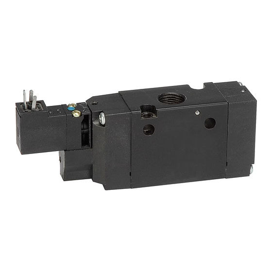
V367eP
"B5" Low Watt & Remote Pilot
Series Valves
ISSueD: September , 2006
Supersedes: March , 2005
Doc. # V-367P, eCN# 060870, Rev. 7
NOte: Solenoid operated valves specified for external pilot or
double air pilot operated valves may have pressures down
to vacuum in the main valve. External pilot pressure must
be greater than or equal to that in the main valve, but not
exceed the ranges above.
Ambient temperature Range: -15°C to 49°C (5°F to 120°F)
Voltage Range: Rated Voltage +10, -15%
CAutION: An interruption of 10 milliseconds or greater to
!
the power supplied to the solenoid of a solenoid operated
valve may cause the valve to shift. Provision must be made
to prevent power interruption of this duration to avoid
unintended, potentially hazardous, consequences.
Lubrication
Filtered and lubricated air is necessary for maximum valve life and
minimum maintenance. If in-service lubrication is used, lubricate
with a straight paraffin based mineral oil having an ISO viscosity
grade of 32 (e.g. Sunvis 932).
NOte: Once in-service lubrication is initiated, the practice should
be continued in order to maximize valve life.
Maintenance & trouble Shooting Hints
Valve Not Shifting Completely When Energized:
1. Check to insure that the proper voltage is supplied to the
solenoids.
2. Check to insure that supply pressure is 138 kPa (20 PSIG) or
greater at the valve's inlet when shifting valve.
3. Check for possible restrictions in air supply, such as undersized
hoses, fittings, or quick disconnects.
4. Check to insure that the spool moves smoothly.
5. Check spool seals for proper installation, dirt, or damage.
WARNING
!
FAILuRe OR IMPROPeR SeLeCtION OR IMPROPeR uSe OF tHe
PRODuCtS AND/OR SYSteMS DeSCRIBeD HeReIN OR ReLAteD IteMS
CAN CAuSe DeAtH, PeRSONAL INJuRY AND PROPeRtY DAMAGe.
This document and other information from Parker Hannifin Corporation, its
subsidiaries and authorized distributors provide product and/or system options
for further investigation by users having technical expertise. It is important
that you analyze all aspects of your application, including consequences of
any failure and review the information concerning the product or systems
in the current product catalog. Due to the variety of operating conditions
and applications for these products or systems, the user, through its own
analysis and testing, is solely responsible for making the final selection of the
products and systems and assuring that all performance, safety and warning
requirements of the application are met.
The products described herein, including without limitation, product features,
specifications, designs, availability and pricing, are subject to change by Parker
Hannifin Corporation and its subsidiaries at any time without notice.
eXtRA COPIeS OF tHeSe INStRuCtIONS ARe AVAILABLe FOR INCLuSION
IN eQuIPMeNt / MAINteNANCe MANuALS tHAt utILIZe tHeSe PRODuCtS.
CONtACt YOuR LOCAL RePReSeNtAtIVe.
Advertisement

Related Manuals for Parker B5


Summary of Contents for Parker B5
- Page 1 The products described herein, including without limitation, product features, Operating Pressure: specifications, designs, availability and pricing, are subject to change by Parker Hannifin Corporation and its subsidiaries at any time without notice. PSIG eXtRA COPIeS OF tHeSe INStRuCtIONS ARe AVAILABLe FOR INCLuSION Minimum IN eQuIPMeNt / MAINteNANCe MANuALS tHAt utILIZe tHeSe PRODuCtS.
- Page 2 “B5” Low Watt & Remote Pilot Series Valves V-367eP Air Leakage through exhaust Ports: Lightly grease with provided lubricant. 1. Check for internal leakage in the cylinder being operated by the Inspect for nicks, scratches, and surface imperfections. If valve.
Need help?
Do you have a question about the B5 and is the answer not in the manual?
Questions and answers