Wavetronix Click 110 Manual
Hide thumbs
Also See for Click 110:
- Installation & quick start manual (2 pages) ,
- User manual (260 pages)
Table of Contents
Advertisement
Quick Links
Using the Click 110
The Click 110 is used to report vehicle data to a MIDAS outstation when used with Wavetronix SmartSensors.
This card plugs directly into an outstation and reports four channels of detection. Because the Click 110 has two
independent serial buses, it can be configured without interfering with data reporting.
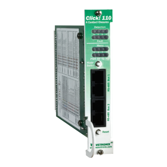
Physical features
The following sections describe the physical features of the Click 110 card.
Click 110
4 Contact Closures
Detection
Detection
Indicators
1
2
3
4
Channel
Indicators
Fault
Menu
LED
1
2
3
4
Indicators
PWR MF TD RD
Mode
Mode Switch
Switch
RS-485
Connectors
Bus 1
RS-485
Connectors
Bus 2
Reset
Reset
Switch
www.wavetronix.com
Communication ports
The Click 110 contains two independent serial communications ports. Each port is made up of two RJ-11
connectors, which make it simple to daisy-chain multiple Click 110 cards together and create a RS-485 bus. The
two RJ-11 RS-485 data buses can be connected to a SmartSensor through a Click 200 surge protection module, or
through a serial data converter.
Typically, one bus is used to report vehicle data, and the other is used for configuration. As both buses are
identical it does not matter which is used for data or configuration. Alternatively, a single bus could be used for
both data and configuration, but data reporting would be temporarily halted during configuration. During this time,
the Click 110 will enter fail-safe mode if vehicle data is not reported for ten seconds.
WX-501-0517 • 05.22
Rack Connector
DIP Switches
0517
1 of 20
Advertisement
Table of Contents

Related Manuals for Wavetronix Click 110


Summary of Contents for Wavetronix Click 110
- Page 1 The Click 110 is used to report vehicle data to a MIDAS outstation when used with Wavetronix SmartSensors. This card plugs directly into an outstation and reports four channels of detection. Because the Click 110 has two independent serial buses, it can be configured without interfering with data reporting.
-
Page 2: Push Buttons
LEDs The faceplate of the Click 110 has four banks of LEDs. The top bank is used for detection indication, the second bank for fault indication, the third for menu indication, and the fourth for menu indication as well as operation states. -
Page 3: Installation And Wiring
DIP switches Just behind the faceplate of the Click 110, on the circuit board, is a set of DIP switches. These switches are used to configure the Click 110 in Hardware mode. All settings, with the exception of Outstation mode and disabling fault latching, are also configurable via Software mode (front panel menu, or Click Supervisor). - Page 4 Click 110 pinout with Peek outstation Description Description Channel 1 fault, normally closed Channel 1, normally closed Channel 1 common No connection Channel 1 fault common Channel 1, normally open Master fault, normally closed No connection No connection No connection...
- Page 5 Click 110 pinout with Siemens outstation Description Description Channel 1 fault, normally open Channel 1, normally closed Channel 1 common No connection Channel 1 fault common Channel 1, normally open Master fault, normally open No connection No connection No connection...
-
Page 6: Fail-Safe Mode
Preparing the SmartSensor In addition to wiring the SmartSensor to the Click 110, you must also make sure that the SmartSensor is configured correctly. Because the Click 110 device receives serial datagrams from the sensor, the sensor must be configured to report data properly for each application. -
Page 7: Dip Switches
DIP switches, as shown in the figure below. The Click 110 features three DIP switches labeled S1, S2, and S3 on the label and in the figure above. (The fourth switch, labeled S4, is currently not used.) Each DIP switch is used to configure one or two different settings, for a... -
Page 8: Channel Enable
S1: Bus 1 baud rate S2: Bus 2 baud rate Value Value – – – Software mode – – – Software mode 9600 bps 9600 bps 19200 bps 19200 bps 38400 bps 38400 bps 57600 bps 57600 bps 9600 bps 9600 bps 9600 bps 9600 bps... - Page 9 Because the Click 110 has four output channels, only four input datagram channels, received from the sensor, can be output by each device. (If you need more than four channels, consider using multiple devices.) As shown in the table below, the outputs are mapped sequentially—that is, they can only be mapped in numerically ordered groups...
-
Page 10: Fault Latch
6 on the S3 DIP switch to tell the Click 110 with which outstation it is going to be used. If S3:6 is off (down), the Click 110 is set to work with a Peek brand outstation. If S3:6 is on (up), the Click 110 is set to work with a Siemens brand outstation. -
Page 11: Front Panel Menu
Menu mode. This section will cover how to use these features and the menu to configure the Click 110. The lower bank of LEDs will be referred to as Level 1 and is used is selecting menu options. The upper bank will be referred to as Level 2 and is used in configuring the menu options. - Page 12 Front panel menu options The following figure documents the menu and configuration options available from the front panel menu. This label is also printed on the side of the Click 110 (on the opposite side from the DIP switches). WX-501-0517 • 05.22...
- Page 13 As mentioned earlier, the Click 110 device receives serial datagrams from a SmartSensor. These datagrams can contain many channels of detection data. Because the Click 110 has four output channels, only four input datagram channels, received from the sensor, can be output by each device. (If you need more than four channels, consider using multiple devices.) As shown in the table below, the outputs are mapped sequentially—that is, they can only...
- Page 14 As each baud rate is attempted, the Level 2 LEDs will sequence with a single LED illuminated from LED 1–4. If the Click 110 is successful in communicating with a SmartSensor, it will display the baud rate found, using the same Level 2 LED system used in selecting the baud rate (covered in the Baud Rate section of this document and the table below).
- Page 15 set to Hardware mode), the Level 2 LED configuration options for that bus will not be displayed (the LED option will never come on). If both RS-485 buses are configured using the DIP switches, the Level 1 LED menu option for autobaud will not be displayed (the green LED option will never come on).
- Page 16 Level 1 LEDs Channel Enable All off (default) Channel 4 on Channel 3 on Channels 3 and 4 on Channel 2 on Channels 2 and 4 on Channels 2 and 3 on Channels 2, 3, and 4 on Level 2 LEDs Channel 1 on Channels 1 and 4 on Channels 1 and 3 on...
-
Page 17: Reset To Default Settings
After the Click 110 has reset to factory defaults, it will check the DIP switches; if any of them are set to Hardware mode, it will apply those settings to the parameter in question. If resetting to factory defaults doesn’t change certain settings the way you expected it to, check the DIP switches to see if they are causing settings to be changed to something other than the default. - Page 18 The Click 110 can be configured using the Expert driver (see the figure below). After you have made configuration changes on the driver and saved it to the Click device, the word “current” will appear after it to indicate the driver is currently loaded onto the device.
- Page 19 Firmware Version Shows the version of firmware your device currently has installed. If Click Supervisor detects a discrepancy between this version and the most current version it currently has access to, you will be prompted to upgrade when you connect to the device. This information cannot be changed. Subnet ID Shows the subnet ID number.
- Page 20 © 2022 Wavetronix LLC. All rights reserved. Protected in the US by patents viewable at www.wavetronix.com/en/legal. Protected by Canadian Patent Nos. 2461411; 2434756; 2512689; and European Patent Nos. 1435036; 1438702; 1611458. Other US and international patents pending. Wavetronix, SmartSensor, Click, Command and all associated logos are trademarks of Wavetronix LLC. All other product or brand names as they appear are trademarks or regis- tered trademarks of their respective holders.
Need help?
Do you have a question about the Click 110 and is the answer not in the manual?
Questions and answers