Sign In
Upload
Manuals
Brands
Teledyne Manuals
Sonar
SeaBat T-Series
Teledyne SeaBat T-Series Manuals
Manuals and User Guides for Teledyne SeaBat T-Series. We have
1
Teledyne SeaBat T-Series manual available for free PDF download: Operator's Manual
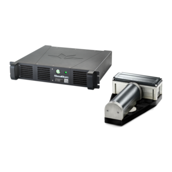
Teledyne SeaBat T-Series Operator's Manual (190 pages)
High-Resolution Multibeam Sonar System
Brand:
Teledyne
| Category:
Sonar
| Size: 47.46 MB
Table of Contents
Table of Contents
5
Introduction
13
System Overview
13
System Architecture
14
Figure 1: Seabat T-Series Rackmount System Configuration
14
Figure 2: Seabat T-Series Rackmount System Configuration with Integrated ins (Optional)
14
System Operation
15
System Features
15
Table 1: Seabat T-Series Rackmount Feature Pack
15
Typical Applications
18
Available Seabat T-Series Rackmount Configurations
19
Table 2: Seabat T-Series Rackmount Available Configurations
19
Safety Precautions
20
Operator Safety
20
Equipment Safety
20
Safe Handling
20
Cleaning and Maintenance
21
Corrosion Avoidance
23
Figure 3: Processor Filter Location
23
Electrical Isolation
24
Exposure to Sunlight
24
Safe Disposal of Waste (WEEE Directive)
24
CE Marking
25
System Startup and Shutdown
26
Chapter Overview
26
System Startup Instructions
27
Starting the Sonar User Interface
27
System Shutdown Instructions
29
System Wake up
30
System Configuration and Operation
31
Chapter Overview
31
Remote Operation
31
Active Sonar Usage
32
Chapter Overview
32
Enhancing Sonar Performance
33
Correct Range Setting
33
Figure 4: Range Setting Diagrams
33
Figure 5: Range Setting - too Long
33
Table 3: Incorrect Range Settings - Examples and Solutions
33
Transmit Power
34
Figure 6: Range Setting - too Short
34
Figure 7: Range Setting - the Exception
34
Ping Rate
35
Receiver Gain
35
Frequency Selection
36
Pulse Length
36
Table 4: TVG Formula
36
Pulse Type
37
Vari-Swath
37
Figure 8: Example of Reduced Swath Width
38
Figure 9: Horizontal Swath Steering
39
Use of Beam Mode
40
Figure 10: Outer Beams for the Different Beam Modes with a Tilted Sonar Head
40
Use of Gates
42
Figure 11: Graphic Illustration of Flexmode
42
Figure 12: Depth Gates, with no Roll
43
Figure 13: Depth Gates, with Roll
43
Figure 14: Depth Gates, with Roll and Motion Sensor Input
44
Figure 15: Depth Gate Tilt
44
Maximizing Quality of Backscatter for Snippets Data
45
Enhancing System Efficiency
45
Multi-Detect Operation
45
Figure 16: Submerged Oil Detected by Multi-Detect
45
Tracker Autopilot
46
Roll Stabilization
46
Figure 17: Swath under Zero Roll Conditions
46
Head Tilt
47
Figure 18: Laterally Displaced Swaths under Roll Conditions
47
Figure 19: Swath under Roll Stabilization
47
Figure 20: Head Tilt Functionality
48
Figure 21: Head Tilt for Harbor Inspection
48
Figure 22: Head Tilt for Pipe Inspection
48
Compensation for Environmental Conditions
49
Loss of Sound by Absorption
49
Loss of Sound by Spreading
50
Figure 23: Acoustic Absorption Reference
50
Sound Velocity
51
Figure 24: Typical Sound Velocity Values
51
Limitations
52
Cavitation
52
Machinery Noise
53
Interference from Other Sonar Systems
53
Speed
53
Air Bubbles
54
Environment
54
System Performance and Data Types
55
Table 5: Seabat T-Series Rackmount System Performance
56
System Components
57
Rack-Mounted Sonar Processor (RSP)
57
Figure 25: Rack-Mounted Sonar Processor
57
EM7218 Receiver Unit
58
EM7219 Receiver Unit (Alternative)
58
TC2181 Projector Unit
58
Figure 26: EM7218 Receiver Unit
58
Figure 27: EM7219 Receiver Unit
58
Figure 28: TC2181 Projector Unit
58
Selectable Beam Density
59
Beam Modes
59
Table 6: Beam Modes with No. of Beams and Swath Coverage
59
Equi-Distant, Equi-Angle, and Intermediate Modes
60
Figure 29: Beam Density
60
Figure 30: Beam Spacing Vs. Beam Angle
60
Figure 31: Beam Spacing
61
Figure 32: Across-Track Sounding Location on a Flat Bottom
61
Data Types
62
Bathymetry Data
62
Side-Scan Data
62
Snippets Backscatter
62
Figure 33: Graphic Illustration of Snippets Data
63
Real-Time Pipe Detection and Tracking
64
Figure 34: Seabat Real-Time Pipe Detection and Tracking
64
Figure 35: Seabat Flexmode
64
Multi-Detect
65
X-Range Performance
65
Full Rate Dual Head
65
Figure 36: Standard Detection
65
Figure 37: Multi-Detect with Enhanced Detail on Quay Wall
65
Figure 38: Multi-Detect
65
Quality
66
Brightness Test
66
Figure 39: Dual Head Synchronization of Pings
66
Figure 40: Brightness Test
66
Colinearity Test
67
Quality Filter
67
Uncertainty Estimation
67
Figure 41: Colinearity Flags
67
Hydrodynamic Drag
68
Drag Simulation Setup
68
Drag Simulation Conclusions
68
Drag Simulation Results
69
Figure 42: T20 Sonar Head Assembly in Bracket with Optional Front Fairing
69
Figure 43: Flow at 10 Knots Around Single T20 with Fairing
69
Figure 44: Flow Around Single T20 with Fairing, Cross Section of Symmetry Plane
69
Figure 45: Flow at 10 Knots Around Single T20 Without Fairing
70
Figure 46: Flow Around Single T20 Without Fairing, Cross Section of Symmetry Plane
70
Figure 47: T20 Dual Sonar Head Assembly in Bracket with Optional Front Fairing
71
Figure 48: Flow at 10 Knots Around Dual T20 with Fairings
71
Figure 49: Flow Around Dual T20 with Fairings, Cross Section of Symmetry Plane
71
Figure 50: Flow at 10 Knots Around Dual T20 Without Fairings
72
Figure 51: Flow Around Dual T20 Without Fairings, Cross Section of Symmetry Plane
72
Figure 52: T50 Sonar Head Assembly in Bracket with Optional Front Fairing
73
Figure 53: Flow at 10 Knots Around Single T50 with Fairing
73
Figure 54: Flow Around Single T50 with Fairing, Cross Section of Symmetry Plane
73
Figure 55: Flow at 10 Knots Around Single T50 Without Fairing
74
Figure 56: Flow Around Single T50 Without Fairing, Cross Section of Symmetry Plane
74
Figure 57: T50 Dual Sonar Head Assembly in Bracket with Optional Front Fairing
75
Figure 58: Flow at 10 Knots Around Dual T50 with Fairings
75
Figure 59: Flow Around Dual T50 with Fairings, Cross Section of Symmetry Plane
75
Figure 60: Flow at 10 Knots Around Dual T50 Without Fairings
76
Figure 61: Flow Around Dual T50 Without Fairings, Cross Section of Symmetry Plane
76
Ping Rate Table
77
Table 7: Ping Rate Table
77
Appendix A Troubleshooting
78
System Error and Warning Messages
78
Error Messages
78
General System Startup Errors
78
Data Reading Errors
79
System Resource Errors
79
Input Signal (Timing and Triggers) Errors
79
Normalization Errors
80
Warning Messages
80
Configuration Warnings
80
Data Processing Warnings
80
Data Recording Warnings
81
BITE Data Warnings
81
Input Signal Warnings
81
System Stability Warnings
81
Data Subscription Warnings
82
Network Components Warnings
82
External Trigger Warnings
82
Error Messages - Master List in Alphabetical Order
83
Warning Messages - Master List in Alphabetical Order
86
Appendix Binstallation Instructions
90
Components List
90
Table 8: Seabat T-Series Rackmount Components
90
Installation Checklist
92
System Interfacing
93
Interfacing Diagram for Standard Configurations
93
Figure 62: T20/50-R, Single/Dual-Head Interfacing Diagram
94
Interfacing Diagram for Configurations with Integrated ins
95
Figure 63: T20/50-R with Integrated INS, Single/Dual-Head Interfacing Diagram
96
Dry-End Installation
97
Rack-Mounted Sonar Processor (RSP)
97
Sonar Processor Mounting
97
Table 9: RSP Technical Specifications
97
Sonar Processor Cable Connections
98
Figure 64: RSP Standard Configuration - Cable Connections
98
Figure 65: RSP ins Configuration (Optional) - Cable Connections
98
Rack-Mounted Sonar Processor Power Button and BITE LED
99
Auxiliary Sensors
100
Standard Seabat T20/50-R Configurations
100
Figure 66: SVP, Motion, and Time Standard Connections
100
Seabat T20/50-R Configurations with Integrated ins
101
Sound Velocity Input
101
Time Input
101
Figure 67: SVP, Motion, and Time Connections with Integrated ins (Optional)
101
Table 10: RSP Port "SVP Com 3
101
Table 11: RSP Port "Time in Com 1
101
Time Output (for Optional ins Configurations)
102
Motion Input
102
Motion Output (for Optional ins Configurations)
102
Standard Serial Ports
102
Table 12: RSP Port "Time out Com 1" for Optional ins
102
Table 13: RSP Port "Motion in Com 2
102
Table 14: RSP Port "Motion out Com 2" for Optional ins
102
Table 15: RSP Ports "Com 4", "Com 3-5" for Optional ins
102
Seabat T-Series Rackmount Cables
103
Figure 68: Seabat T-Series Rackmount System Cables
103
Wet-End Installation
104
EM7218 Receiver Unit (PN 85002409)
104
EM7219 Receiver Unit (PN 85002436)
104
Table 16: EM7218 Receiver Unit Technical Specifications
104
Table 17: EM7219 Receiver Unit Technical Specifications
104
TC2181 Projector Unit (PN 85002319)
105
Wet-End Cable Connections
105
Table 18: TC2181 Projector Unit Technical Specifications
105
Sonar Head Assembly Orientation
106
Sonar Reference Point
106
Wet-End Mounting
107
Hardware
108
System Check
109
Appendix Cpps in and Trigger in
110
Electrical Specifications for PPS in and Trigger in
110
Typical PPS in and Trigger Performance
110
Figure 69: Required PPS Pulse Width
110
Table 19: PPS in and Trigger in Signals
110
Hints and Advice
111
Figure 70: PPS in Delay
111
Figure 71: Pps/Trigger Signal
111
Appendix Ddata Rates
112
Table 20: Theoretical Max. Data Rates - Seabat T-Series Rackmount Single and Dual Head
112
Appendix Enetwork Configuration
113
System Network Configuration
113
Change IP Configuration
113
Table 21: IP Configuration for RSP
113
Appendix F Configuration of Integrated ins (Optional)
115
POS MV - How to Perform a GAMS Calibration
115
MV-Posview - Standby Mode
115
GAMS Parameter Setup
115
Positioning Quality
116
GAMS Calibration - Procedure
117
POS MV - How to Set up for a Multibeam Survey
121
Conventions
121
Coordinate Frames
121
Figure 72: Tate/Bryant Co-Ordinate/Rotation System
121
Offsets - Example
122
Figure 73: Vessel Outline - Example
122
Table 22: Sensor Offsets
122
Alignments - Example
123
MV-Posview Software
123
Table 23: Sensor Alignments
123
Installation Parameters - Lever Arms & Mounting Angles
124
Reference Point
124
Installation Parameters - Sensor Mounting
125
Figure 74: IMU Misalignment - Example
125
Installation Parameters - Tags, Multipath & Autostart
126
Installation Parameters - Heave Filter
126
POS MV Output- Serial Data
127
Table 24: POS MV Output Serial Data - COM Ports 1-2
127
POS MV Output- Ethernet Realtime
129
Acquisition Software
129
Patch Test Results
129
POS Statistics
130
Appendix Ginterfacing Sensors to Teledyne Pds
131
Establishing a Connection to the RSP
131
Interfacing to Teledyne PDS
133
Configuring the Sonar UI to Output Data
133
Configuring Teledyne PDS
134
Appendix H Reference Documentation
137
Seabat T-Series Rackmount Documentation
137
Figure 75: System Documentation Link (Example Only)
137
Seabat T-Series Rackmount Design Documents
138
Table 25: Seabat T-Series Rackmount Design Documents
138
Receiver, EM7219 Outline
140
Figure 76: Receiver, EM7219 Outline
140
Receiver, EM7218 Outline
141
Figure 77: Receiver, EM7218 Outline
141
Projector, TC2181 Outline
142
Figure 78: Projector, TC2181 Outline
142
T20: Receiver EM7219 and Projector TC2181, Bracket Installation
143
Figure 79: T20: Receiver EM7219 and Projector TC2181, Bracket Installation
143
T20 Bracket Installation: Sonar Reference Point
144
Figure 80: T20 Bracket Installation: Sonar Reference Point
144
T20 Bracket Installation with IMU Reference Point
145
Figure 81: T20 Bracket Installation with IMU Reference Point
145
T20 Bracket Installation with Fairing (Optional)
146
Figure 82: T20 Bracket Installation with Fairing (Optional)
146
T50: Receiver EM7218 and Projector TC2181, Bracket Installation
147
Figure 83: T50: Receiver EM7218 and Projector TC2181, Bracket Installation
147
T50 Bracket Installation: Sonar Reference Point
148
Figure 84: T50 Bracket Installation: Sonar Reference Point
148
T50 Bracket Installation with IMU Reference Point
149
Figure 85: T50 Bracket Installation with IMU Reference Point
149
T50 Bracket Installation with Fairing (Optional)
150
Figure 86: T50 Bracket Installation with Fairing (Optional)
150
T20 Dual Head Bracket Installation (Optional)
151
Figure 87: T20 Dual Head Bracket Installation (Optional)
151
T20 Dual Head Bracket Installation (Optional): Sonar Reference Point
152
Figure 88: T20 Dual Head Bracket Installation (Optional): Sonar Reference Point
152
T20 Dual Head Bracket Installation with Fairing (Optional)
153
Figure 89: T20 Dual Head Bracket Installation with Fairing (Optional)
153
T20 Dual Head Bracket Installation with IMU Reference Points (Optional)
154
Figure 90: T20 Dual Head Bracket Installation with IMU Reference Points (Optional)
154
Narrow Head Adaptor (Optional) for T20 Dual Head. Outline Assembly Drawing
155
Figure 91: Narrow Head Adaptor (Optional) for T20 Dual Head. Outline Assembly Drawing
155
Narrow Head Adaptor (Optional) for T20 Dual Head. Outline
156
Figure 92: Narrow Head Adaptor (Optional) for T20 Dual Head. Outline
156
Narrow Head Adaptor (Optional) for T20 Dual Head. Outline with Fairing
157
Figure 93: Narrow Head Adaptor (Optional) for T20 Dual Head. Outline with Fairing
157
Narrow Head Adaptor (Optional) for T20 Dual Head. Sonar Reference Point
158
Figure 94: Narrow Head Adaptor (Optional) for T20 Dual Head. Sonar Reference Point
158
Narrow Head Adaptor (Optional) for T20 Dual Head with IMU. Sonar Reference Point
159
T50 Dual Head Bracket Installation (Optional)
160
Figure 96: T50 Dual Head Bracket Installation (Optional)
160
T50 Dual Head Bracket Installation (Optional): Sonar Reference Point
161
Figure 97: T50 Dual Head Bracket Installation (Optional): Sonar Reference Point
161
T50 Dual Head Bracket Installation with Fairing (Optional)
162
Figure 98: T50 Dual Head Bracket Installation with Fairing (Optional)
162
T50 Dual Head Bracket Installation with IMU Reference Points (Optional)
163
Seabat T-Series Rackmount Operator's Manual
163
Figure 99: T50 Dual Head Bracket Installation with IMU Reference Points (Optional)
163
T50: Receiver EM7218 and Projector TC2187 (Optional), Bracket Installation with
164
Svp 70
164
Figure 100: T50: Receiver EM7218 and Projector TC2187 (Optional), Bracket Installation with
164
T50: Receiver EM7218 and Projector TC2187 (Optional), Bracket Installation with SVP 70 and Fairing
165
Figure 101: T50: Receiver EM7218 and Projector TC2187 (Optional), Bracket Installation with
165
T50: Receiver EM7218 and Projector TC2187 (Optional), Bracket Installation, Sonar Reference Point
166
Figure 102: T50: Receiver EM7218 and Projector TC2187 (Optional), Bracket Installation, Sonar
166
T50: Receiver EM7218 and Projector TC2187 (Optional), Bracket Installation, IMU Reference Point
167
Figure 103: T50: Receiver EM7218 and Projector TC2187 (Optional), Bracket Installation, IMU
167
Cable Assembly, Rack-Mounted Sonar Processor to Receiver
168
Figure 104: Cable Assembly, Rack-Mounted Sonar Processor to Receiver
168
Cable Assembly, Rack-Mounted Sonar Processor to Projector
169
Figure 105: Cable Assembly, Rack-Mounted Sonar Processor to Projector
169
Cable Assembly, Rack-Mounted Sonar Processor to Projector
170
Figure 106: Rack-Mounted Sonar Processor
170
Rack-Mounted Sonar Processor with ins (Optional)
171
Figure 107: Rack-Mounted Sonar Processor with ins (Optional)
171
IMU Outline (Optional)
172
Figure 108: IMU Outline (Optional)
172
IMU Motion Reference Points on T-Series Brackets (Optional)
173
Figure 109: IMU Motion Reference Points on T-Series Brackets (Optional)
173
IMU Cable
174
Figure 110: IMU Cable
174
Antenna Outline
175
Figure 111: Antenna Outline
175
Antenna Cable
176
Figure 112: Antenna Cable
176
Cable Assembly, Sonar Processor to SVP 70 (Optional)
177
Figure 113: Cable Assembly, Sonar Processor to SVP 70 (Optional)
177
Cable Assembly, Sonar Processor to SVP 71 (Optional)
178
Figure 114: Cable Assembly, Sonar Processor to SVP 71 (Optional)
178
7Kcenter Licenses - Copyright Information
179
Table 26: LAPACK - Copyright Information
179
Table 27: Winpcap - Copyright Information
180
Appendix Iseabat T-Series Rackmount System Options
184
Dual-Head Brackets
184
Extended Range Projector
184
System Performance
184
Figure 115: TC2187 Projector
184
Table 28: TC2187 Projector
184
Table 29: Seabat T50 Extended Range - System Performance
184
Mounting Bracket
185
Extended Warranty Contract
185
Fairings
185
Integrated Inertial Navigation System
185
Seabat Cables
185
Service Level Agreement
185
Sound Velocity Probe
186
System Integration and Training
186
Teledyne PDS Data Acquisition Software
186
Table 30: SVP Technical Specifications
186
Appendix Jstandard Warranty Information
187
One-Year Limited Warranty
187
Warranty Exclusions
187
Warranty Disclaimer
187
Servicing During Warranty Period
187
Equipment Return Procedure
188
Teledyne RESON Support
188
Advertisement
Advertisement
Related Products
Teledyne SeaBat UI
Teledyne SeaBat T Series
Teledyne SG-14
Teledyne SFG-205
Teledyne SDG1000 Series
Teledyne SDG1005
Teledyne STREAMPRO
Teledyne SP-F-SIM
Teledyne FLIR Si124 Series
Teledyne Si124-LD Plus
Teledyne Categories
Measuring Instruments
Analytical Instruments
Digital Camera
Test Equipment
Laboratory Equipment
More Teledyne Manuals
Login
Sign In
OR
Sign in with Facebook
Sign in with Google
Upload manual
Upload from disk
Upload from URL