Table of Contents
Advertisement
Quick Links
TECHNICAL SPECIFICATION
Type Identification Value:
System Compatibility:
Environment:
Operating Temperature:
Storage Temperature:
Operating Humidity:
Dimensions (HxWxD):
Mounting Requirements:
Battery Requirements:
Standby Current:
Alarm Current:
Addressable Device Condi-
tions:
Relay Contact Rating:
+
Note: The module must not be used to switch mains voltages
Recommended Wire Size:
Electromagnetic Compatibility
The FC410RIM complies with the following:
Ø product family standard EN50130-4 in respect of Conducted Distur-
bances, Radiated Immunity, Electrostatic Discharge, Fast Transients
and Slow High Energy;
Ø EN50081-1 for emissions.
INTRODUCTION
The FC410RIM Relay Interface Module provides one volt-free relay change-
over contact on a latching relay. The relay is controlled by a command sent
from the FC fire controller via the addressable loop. The relay state (acti-
vated, deactivated or stuck) is returned to the controller.
FEATURES
FC410RIM features include the following:
Ø Addressable functionality.
The control panel sends a command to operate the relay, then reports an
activated or deactivated state back to the panel through the use of a set of
contacts dedicated to monitor the state of the relay.
Ø One volt-free dry contact relay output.
Ø Output to drive a high voltage relay HVR800.
Ø LED status indicator which is normally off. When the FC410RIM receives
a command to activate, the LED lights.
WIRING & INSTALLATION NOTES
!
CAUTION:THE O+ AND O- TERMINALS MUST NOT BE USED.FOR
CONNECTING THE FC410RIM TO AN HVR800, SEE PUBLICATION
17A-03-HVR OR 120-415-528.
The following notes apply:
1)
There are no user-required settings (switches, headers) on the
FC410RIM. All wiring must be free of earths.
2)
All wiring must conform to the applicable standards.
3)
See Figure 4 for FC410RIM Simplified Wiring Diagram.
4)
For 24V dc powered applications, only use a regulated supply suitable
for fire protective signalling service.
5)
For powered circuit operation, route the positive conductor through the
FC410RIM to the external device, while connecting the common (neu-
tral) conductor to the external circuit.
161
Use only with FC Fire Alarm Controllers
Indoor Application only
o
-25 to +70
C
o
-40 to +80
C
Up to 95% non-condensing
87 x 148 x 14 mm
One FC backbox surface mount
0.46mA max
4.5mA max
– Normal
– Active
– Output Stuck
– Device Type Invalid
– Device No Response
DC – 2A @ 24V dc
Min. 1.5 mm
2
Max. 2.5 mm
2
ENGLISH
6)
For dry contact switching, connect the external circuit to the COM and N/O
or N/C terminals for normally open or normally closed operation as required.
7)
Verify that relay wiring is correct for the FC410RIM before connecting to
the addressable loop circuit.
8)
For connection to an HVR800 High Voltage Relay Module, refer to In-
stallation Sheet 17A-03-HVR or 120-415-528.
INSTALLATION TO FC470CV DOUBLE GANG COVER
1)
Assemble the FC410RIM to FC470CV Double Gang cover, using the
four screws and washers provided.
2)
Snap on the ancillary housing PCB cover.
3)
Fit cover onto FC backbox.
ADDRESS SETTINGS
The FC410RIM has a default factory set address of 255, this must be set to
the loop address of the device using the FC490ST Loop Service Tool. The
FC410RIM may be programmed with the address prior to being installed by
using the internal programming port (see Fig.2) or after being installed by
using the programming port on the front cover (see Fig.3).
+
Note: once the address has been programmed, take note of the device
location and address number, to include on site drawings.
CABLING
The maximum section of the cable that can be connected at any one termi-
nal is 2.5mm
2
. The section is calculated based on the characteristics of the
cable and the load.
ORDERING INFORMATION
FC410RIM: Relay Input Module:
FC470CV:
Double-Gang cover
RECYCLING INFORMATION
Customers are recommended to dispose of their used equipments (panels,
detectors, sirens, and other devices) in an environmentally sound manner.
Potential methods include reuse of parts or whole products and recycling of
products, components, and/or materials.
WASTE ELECTRICAL AND ELECTRONIC EQUIPMENT (WEEE)
DIRECTIVE
In the European Union, this label indicates that this product
should NOT be disposed of with household waste. It should be
deposited at an appropriate facility to enable recovery and re-
cycling.
The manufacturer reserves the right to change the technical specifications
of this product without prior notice.
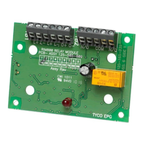
FIG. 1
FC410RIM Relay Interface Module
Advertisement
Table of Contents

Subscribe to Our Youtube Channel
Related Manuals for Tyco FC410RIM


Summary of Contents for Tyco FC410RIM
- Page 1 Addressable Device Condi- ADDRESS SETTINGS tions: – Normal The FC410RIM has a default factory set address of 255, this must be set to – Active the loop address of the device using the FC490ST Loop Service Tool. The – Output Stuck FC410RIM may be programmed with the address prior to being installed by –...
- Page 2 L+ L- L+ L- O+ O- PORTA DI PROGRAMMAZIONE PROGRAMMING PORT PROGRAMMIERANSCHLUSS PORTA DI PROGRAMMAZIONE ADDRESS SETTING PORT PROGRAMMIERANSCHLUSS FIG. 2 FC410RIM fissata al coperchio FIG. 3 FC410RIM Placca FC410RIM fitted to cover Facia Plate FC410RIM ins Gehäuse eingebaut Kurzschlussisolator Vorderseite RIGHT...
Need help?
Do you have a question about the FC410RIM and is the answer not in the manual?
Questions and answers