Advertisement
Quick Links
The Future of Analog IC Technology
DESCRIPTION
The MP2483 is a 55V, 2.5A, white LED driver
suitable for either step-down or inverting
step-up/down applications. It achieves 2.5A
peak output current over a wide input supply
range with excellent load and line regulation.
Current mode operation provides fast transient
response and eases loop stabilization. Fault
condition protection includes thermal shutdown,
cycle-by-cycle peak current limiting, input over
voltage protection, open strings protection and
output short circuit protection.
The MP2483 incorporates both DC and PWM
dimming onto a single control pin. The separate
input reference ground pin allows for direct
enable and/or dimming control for a positive to
negative power conversion.
The MP2483 requires a minimum number of
readily available standard external components
and is available in 10-pin 3mm x 3mm QFN
packages.
MP2483DQ DEMO BOARDS
Board number
EV2483DQ-00A
EV2483DQ-00B
EV2483DQ-00C
ELECTRICAL SPECIFICATIONS
Parameter
Input Voltage
LEDs #
LED Current
EV2483DQ-00C Rev.1.1
04/26/2010
Arrow.com.
Downloaded from
Operating
Input
LED#
Mode
(V)
Buck
15~50
Buck-boost
12
3~5
Boost
12
6~9
Symbol
Value
V
12
IN
6~9
I
500
LED
MPS Proprietary Information. Patent Protected. Unauthorized Photocopy and Duplication Prohibited.
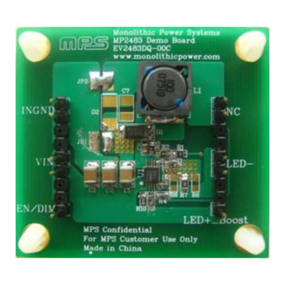
2.5A, 55V, Programmable Frequency
White LED Driver Evaluation Board
FEATURES
•
2.5A Maximum Output Current
•
Unique Step-up/down Operation (Buck-
Boost Mode)
•
Wide 4.5V to 55V Operating Input Range for
Step-Down Applications (Buck Mode)
•
0.28Ω Internal Power MOSFET Switch
•
Adjustable Switching Frequency
•
Analog and PWM Dimming
•
0.198V Reference Voltage
•
5μA Shutdown Mode
•
No minimum LED required
•
Stable with Low ESR Output Ceramic
Capacitors
•
Cycle-by-Cycle Over Current Protection
•
Thermal Shutdown Protection
•
Open Strings Protection
•
Input Over Voltage Protection
•
Output Short Circuit Protection
•
Available in 10-Pin 3x3 QFN Package
APPLICATIONS
•
General LED Illuminations
•
LCD Backlight Panels
ILED
•
Handheld Computers
(mA)
•
Automotive Internal Lighting
3
700
•
Portable Multimedia Players
500
•
Portable GPS Devices
500
For MPS green status, please visit MPS website under Quality Assurance.
"MPS" and "The Future of Analog IC Technology" are Registered Trademarks of
Monolithic Power Systems, Inc.
Units
V
mA
www.MonolithicPower.com
© 2013 MPS. All Rights Reserved.
EV2483DQ-00C
1
Advertisement

Related Manuals for MPS EV2483DQ-00C


Summary of Contents for MPS EV2483DQ-00C
- Page 1 Buck-boost • Portable GPS Devices EV2483DQ-00C Boost For MPS green status, please visit MPS website under Quality Assurance. “MPS” and “The Future of Analog IC Technology” are Registered Trademarks of Monolithic Power Systems, Inc. ELECTRICAL SPECIFICATIONS Parameter Symbol Value Units...
- Page 2 (L x W x H) 5cm x 4.5cm x 0.7cm Board Number MPS IC Number EV2483DQ-00C MP2483DQ EV2483DQ-00C Rev.1.1 www.MonolithicPower.com 04/26/2010 MPS Proprietary Information. Patent Protected. Unauthorized Photocopy and Duplication Prohibited. © 2013 MPS. All Rights Reserved. Arrow.com. Arrow.com. Downloaded from Downloaded from...
-
Page 3: Evaluation Board Schematic
MPS WLED Driver, 2.5A, MP24 55V, QFN3*3 MP2483DQ 83DQ frequency programmable EV2483DQ-00C Rev.1.1 www.MonolithicPower.com 04/26/2010 MPS Proprietary Information. Patent Protected. Unauthorized Photocopy and Duplication Prohibited. © 2013 MPS. All Rights Reserved. Arrow.com. Arrow.com. Arrow.com. Downloaded from Downloaded from Downloaded from... -
Page 4: Printed Circuit Board Layout
EV2483DQ-00C 2.5A, 55V, PROGRAMMABLE FREQUENCY WHITE LED DRIVER PRINTED CIRCUIT BOARD LAYOUT Figure 1—Top Layer Figure 2—Bottom Layer EV2483DQ-00C Rev.1.1 www.MonolithicPower.com 04/26/2010 MPS Proprietary Information. Patent Protected. Unauthorized Photocopy and Duplication Prohibited. © 2013 MPS. All Rights Reserved. Arrow.com. Arrow.com. Arrow.com. Arrow.com. Downloaded from... - Page 5 4. Power up the input voltage source, and then power up the EN/Dim signal, the LEDs should be ignited. NOTICE: The information in this document is subject to change without notice. Please contact MPS for current specifications. Users should warrant and guarantee that third party Intellectual Property rights are not infringed upon when integrating MPS products into any application.
Need help?
Do you have a question about the EV2483DQ-00C and is the answer not in the manual?
Questions and answers