Advertisement
Quick Links
The Future of Analog IC Technology
DESCRIPTION
The EV2690-R-00A is the evaluation board
designed to demonstrate the capabilities of
MPS' MP2690, a highly-integrated, flexible
switch-mode battery charge management for a
single-cell Li-ion and Li-Polymer battery used in
a wide range of applications.
EV2690 uses two operating modes—charge
mode and boost mode—to allow management
of system and battery power based on the state
of the input.
When input power is present, the board
charges
a
single-cell
programmable charge current of up to 2.5A.
In the absence of an input source, the board
switches to boost mode through the PB pin to
power the SYS pins from the battery with a
current of up to 2.1A.
The evaluation board provides 4-LED to
achieve the voltage based fuel gauge indication
and distinguish charge mode from boost mode.
To guarantee safe operation, the EV2690 has
input-over-voltage
protection,
voltage protection, thermal shutdown, battery-
temperature monitoring, and a programmable
timer to prevent prolonged charging of a dead
battery.
ELECTRICAL SPECIFICATION
Parameter
Symbol
Charge Mode
Input Voltage Range
V
Charge-Full Voltage
Charge Current
Input Current Limit
Boost Mode
Battery Voltage
SYS Voltage
Regulation
SYS Output Current
Limit
EV2690-R-00A Rev. 1.0
9/25/2015
MPS Proprietary Information. Patent Protected. Unauthorized Photocopy and Duplication Prohibited.
battery
with
battery
over-
Value
Units
V
4.55 – 6
V
IN
4.2 / 4.35
BATT_Full
V
/ 4.45
I
2.5
A
CHG
I
2.7
A
IN_LIM
V
3-4.5
V
BATT
V
SYS
5
V
I
SYS
2.1
A
www.MonolithicPower.com
© 2015 MPS. All Rights Reserved.
Evaluation Board of All-in-one 2.5A
Battery Charge and 2.1A Boost Discharge
FEATURES
4.55V-to-6V Operating Input Voltage Range
Power Management Function Integrated
Input-Current-Limit
Regulation
Up to 2.5A Programmable Charge Current
Selectable 4.45V / 4.35V / 4.2V Charge
Voltage with 0.5% Accuracy
Battery Temperature Monitoring
4-LED for battery fuel gauge indication
Programmable Timer Back-Up Protection
Battery-Reverse-Leakage Blocking
Reverse-Boost-Operation
a
System
Up to 94% 5V Boost Mode Efficiency @
2.1A with BATT=4.5V
Up to 2.1A Programmable Output Current
Limit in Boost Mode
APPLICATIONS
Sub-battery Applications
Power-bank Applications for Smart-Phone,
Tablet and Other Portable Devices
All MPS parts are lead-free, halogen free, and adhere to the RoHS
directive. For MPS green status, please visit MPS website under Quality
Assurance.
"MPS" and "The Future of Analog IC Technology" are Registered
Trademarks of Monolithic Power Systems, Inc.
EV2690-R-00A
and
Input
for
Powering
Voltage
1
Advertisement

Subscribe to Our Youtube Channel
Related Manuals for MPS EV2690-R-00A


Summary of Contents for MPS EV2690-R-00A
- Page 1 Tablet and Other Portable Devices input-over-voltage protection, battery over- All MPS parts are lead-free, halogen free, and adhere to the RoHS voltage protection, thermal shutdown, battery- directive. For MPS green status, please visit MPS website under Quality Assurance. temperature monitoring, and a programmable “MPS”...
-
Page 2: Evaluation Board Schematic
LED2 2K R8 ROLIM OLIM LED3 LED3 2K R9 71.5K RISET LED4 LED4 2K R10 ISET 60.4K CTMR 100nF EV2690-R-00A Rev. 1.0 www.MonolithicPower.com 9/25/2015 MPS Proprietary Information. Patent Protected. Unauthorized Photocopy and Duplication Prohibited. © 2015 MPS. All Rights Reserved. - Page 3 Inductor;2.2uH;0.173m;8.2A SPM6530T-2R2M Micro-USB receptacle MP2690 IC QFN26 4*4 MP2690GR USB A-type receptacle Push Button; SM 4x10mm;1.5mm Switching Height button EV2690-R-00A Rev. 1.0 www.MonolithicPower.com 9/25/2015 MPS Proprietary Information. Patent Protected. Unauthorized Photocopy and Duplication Prohibited. © 2015 MPS. All Rights Reserved.
-
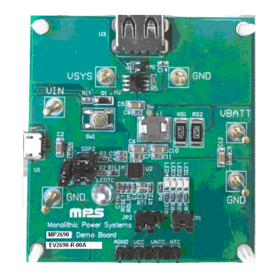
Page 4: Printed Circuit Board Layout
EV2690-R-00A – 2.5A CHARGER, 2.1A BOOST DISCHARGE, ALL-IN-ONE PRINTED CIRCUIT BOARD LAYOUT Figure 1: Top Silkscreen Layer Figure 2: Top Layer Figure 3: Bottom Layer EV2690-R-00A Rev. 1.0 www.MonolithicPower.com 9/25/2015 MPS Proprietary Information. Patent Protected. Unauthorized Photocopy and Duplication Prohibited. © 2015 MPS. All Rights Reserved. - Page 5 (k ) RS1(m ) OLIM For the other detailed description on the operation of the MP2690, please refer to the datasheet. EV2690-R-00A Rev. 1.0 www.MonolithicPower.com 9/25/2015 MPS Proprietary Information. Patent Protected. Unauthorized Photocopy and Duplication Prohibited. © 2015 MPS. All Rights Reserved.
-
Page 6: Equipment Requirement
Turn on the DC power source. The charger will start. Use the oscilloscope to verify that the 2.5A charge current is being delivered to the battery. Figure 4: Setup for Charge Mode EV2690-R-00A Rev. 1.0 www.MonolithicPower.com 9/25/2015 MPS Proprietary Information. Patent Protected. Unauthorized Photocopy and Duplication Prohibited. © 2015 MPS. All Rights Reserved. - Page 7 NOTICE: The information in this document is subject to change without notice. Users should warrant and guarantee that third party Intellectual Property rights are not infringed upon when integrating MPS products into any application. MPS will not assume any legal responsibility for any said applications.
Need help?
Do you have a question about the EV2690-R-00A and is the answer not in the manual?
Questions and answers