Advertisement
Quick Links
QUICK START MANUAL
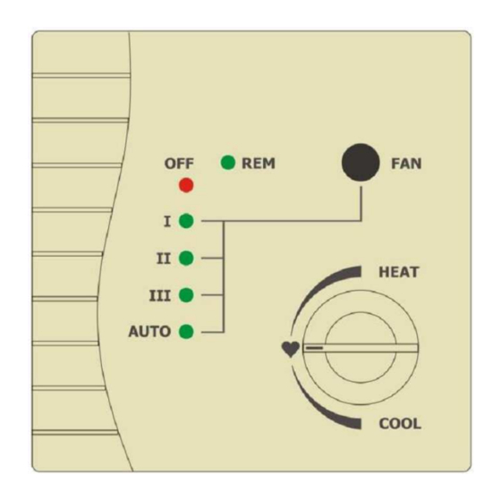
Easy Wall Controller (EWC) KBRCS01A
Easy Wall Controller (EWC) provides:
- Room temperature measuring
- LOCAL / REMOTE control mode
- I, II, III, AUTO fan modes
- A/C system Switch ON/OFF
- Turning the dial for temperature variation
Common features:
- Wall mounted Easy Wall Controller powered from Online Controller
- Modbus communication protocol
(See Figure 3 – pin-out assignment)
Mounting:
- wall mounting in dry internal environment
- approximately 1.5 m above the floor in a place with good air circulation
- do not mount where it can be affected by a draught, sunshine, heating devices or other factors
Installation:
This device may be installed only by an authorised person for the installation and service of Daikin A/C units. Please
follow the safety instructions in the A/C unit manual.
1. Turn OFF the Online Controller - unplug Online
Controller system cable or turn the A/C isolator OFF
(NOT only ON/OFF button on A/C front panel).
2. Remove EWC front panel by pressing the two pawls
on bottom or top side (e.g. by screwdriver). See
Figure 2.
Figure 2
3. Mount back panel on the selected place on the wall.
4. Connect Online Controller and EWC via the cable.
Look at Figure 3 for pin-out assignment.
5. Then turn ON the Online Controller - connect Online
Controller system cable or turn the A/C isolator ON.
6. Set the communication parameters (Parity, Address, Communications rate, RS485 Line Termination) of EWC via
configuration jumpers (Figures 4 and 5).
Parity must be set to Even.
Procedure:
Address has to be set from 0 to 63. The weight of individual
jumpers (IJ) for addressing and communication rate settings is
listed on Figure 5. Procedure:
Communication rate must be set to 38400 bps.
Figure 1
Procedure:
jumper JP7 must be open – remove it.
RS485 line Termination. Procedure:
7. Open SETUP menu of Online Controller (via
web browser, for detailed instruction, please
read the Quick Start manual of the Online
Controller). At Modbus devices setup page
(Figure 7) choose EWC35 from Wall
controller selection box and insert Modbus
Figure 3
address 8. Confirm your selection with the
Set button.
a) Take out jumpers from JP1 to JP8 (LEDs are flickering irregularly under power supply)
b) Place jumper on position JP1 (Even parity)
c) Place jumper on position JP8 for confirm
Even parity (LEDs switch OFF)
a) Place jumper on the position JP4 for the address 8.
a) The jumper on position JP8 must be closed and
a) Keep the jumpers J10 and J11 unconnected on the intermediate station or connect them on the end
station. See Figure 6.
Figure 5
Figure 6
Figure 7
Figure 4
Advertisement

Summary of Contents for Daikin KBRCS01A
- Page 1 Keep the jumpers J10 and J11 unconnected on the intermediate station or connect them on the end station. See Figure 6. This device may be installed only by an authorised person for the installation and service of Daikin A/C units. Please follow the safety instructions in the A/C unit manual.
- Page 2 Heating – max = 30 Heating – min = 10 Average value = 0,5 * (30+10) = 20 CONTINEO, s.r.o. and COLTBURG, s.r.o. declare that the product KBRCS01A is in identity Calculation of displayed temperature value with requirement and other clauses of directive 1999/5/EC.


