Table of Contents
Advertisement
Quick Links
Advertisement
Table of Contents

Related Manuals for HMS HMS-EN2MB-R


Summary of Contents for HMS HMS-EN2MB-R
- Page 1 User Manual EtherNet/IP to Modbus-TCP Linking Device Doc.Id. SCM-1202-008 Rev. 1.1 Connecting Devices HMS Industrial Networks Mailing address: Box 4126, 300 04 Halmstad, Sweden E-mail: info@hms-networks.com Visiting address: Stationsgatan 37, Halmstad, Sweden Web: www.anybus.com...
- Page 2 Liability Every care has been taken in the preparation of this manual. Please inform HMS Industrial Networks AB of any inaccuracies or omissions. The data and illustrations found in this document are not binding. We, HMS Industrial Networks AB, reserve the right to modify our products in line with our policy of continuous product development.
-
Page 3: Table Of Contents
Control/Status Word........................ 10 Live List ............................11 Transaction Status List ......................12 Exception Code List ......................... 13 Chapter 2 About the HMS-EN2MB-R Linking Device........14 External View ..........................14 Mounting the Linking Device ....................15 DIN-rail Mounting ......................15 Wall Mounting......................... 16 Status LEDs .......................... - Page 4 Configuration ..........................41 Authentication ........................41 Modbus Client ........................42 Modbus Servers......................... 43 EtherNet/IP (Adapter Interface)..................46 Tools............................47 HMS-EN2MB-R Management ..................47 Backup and Restore ......................47 Mapping Overview ......................48 Transaction Monitor ......................49 Chapter 8 CIP Objects ..................50 General Information .........................
- Page 5 Appendix A Technical Specification ..............69 Protective Earth (PE) Requirements..................69 Power Supply ..........................69 Environmental Specification ....................69 Temperature........................69 Relative Humidity......................69 EMC (CE) Compliance ......................70 Appendix B Copyright Notices ................71 EtherNet/IP to Modbus-TCP Linking Device Doc.Id.
-
Page 6: Preface
Preface P. About This Document For more information, documentation etc., please visit the HMS website, www.anybus.com. P.1 Related Documents Document Author Modbus Application Protocol Specification V1.1B Modbus Organization CIP Specification, Vol 1 (CIP Common) & 2 (EtherNet/IP) ODVA P.2 Document History Summary of Recent Changes (1.0... -
Page 7: Ethernet/Ip To Modbus-Tcp Linking Device
The EtherNet/IP to Modbus-TCP linking device features a custom add-on profile (AOP) for easy in- tegration with Studio 5000. Within this add-on profile (AOP), the HMS configuration tool can be launched. When the configuration is ready, it can automatically be translated to structured Studio 5000 controller tags. -
Page 8: Functional Overview
EtherNet/IP to Modbus-TCP Linking Device 8 1.3 Functional Overview Internally, the linking device consists of an intelligent gateway platform, a Modbus-TCP interface and an EtherNet/IP (slave) interface. The Modbus-TCP interface and the EtherNet/IP (slave) interface are interconnected through the intelligent gateway platform, which basically forwards data from one net- work to the other and vice versa as shown below. -
Page 9: Data Exchange
EtherNet/IP to Modbus-TCP Linking Device 9 1.4 Data Exchange Each of the two network interfaces exchanges data on its network through two buffers. The linking de- vice forwards the data between these buffers as shown below. Note that this process is separated from the network data exchange. -
Page 10: I/O Mapped Data
EtherNet/IP to Modbus-TCP Linking Device 10 1.5 I/O Mapped Data I/O mapped data is cyclic data, exchanged between the networks and/or devices at a high transfer rate. It is associated with implicit messaging, where data is continuously sent on the network. 1.6 Parameter Data Parameter data is usually exchanged acyclically to set or change parameters in devices before or during normal process. -
Page 11: Live List
EtherNet/IP to Modbus-TCP Linking Device 11 1.8 Live List The live list features the possibility for the EtherNet/IP network to retrieve a list containing the status of every transaction on the Modbus-TCP network. It is accessible using parameter access, and also I/O mapped by default. The I/O mapped live list can be enabled/disabled when configuring the EtherNet/IP network settings. -
Page 12: Transaction Status List
EtherNet/IP to Modbus-TCP Linking Device 12 1.9 Transaction Status List This list holds information about the transactions between the Modbus network and the linking device, from the perspective of the linking device. It is a list available from the module, which is possibl3e to be retrieved acyclically (using parameter ac- cess) by the EtherNet/IP network. -
Page 13: Exception Code List
EtherNet/IP to Modbus-TCP Linking Device 13 1.10 Exception Code List If Modbus transactions fail, the slaves can respond with an exception code. These can be found in the exception code list available from the module, possible to be retrieved acyclically (using parameter ac- cess) by the EtherNet/IP network. -
Page 14: About The Hms-En2Mb-R Linking Device
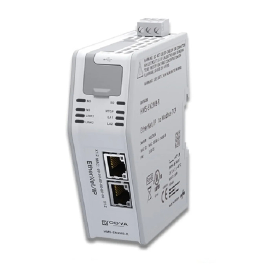
Chapter 2 2. About the HMS-EN2MB-R Linking Device 2.1 External View • A: Power Connector This connector is used to apply power to the linking device. It is also possible to connect protective earth (PE) to the power connector. See “Power Connec- tor”... -
Page 15: Mounting The Linking Device
About the HMS-EN2MB-R Linking Device 15 2.2 Mounting the Linking Device The EtherNet/IP to Modbus-TCP Linking Device can be physically installed either by mounting it onto a DIN-rail or, if installed in areas exposed to vibration, by mounting it on a wall for more stability. -
Page 16: Wall Mounting
About the HMS-EN2MB-R Linking Device 16 2.2.2 Wall Mounting Use the wall mounting option if there is a need to place the linking device in an environment exposed to vibration. This way of mounting the module offers more stability than the traditional DIN-rail mount- ing. -
Page 17: Status Leds
About the HMS-EN2MB-R Linking Device 17 2.3 Status LEDs Note: A test sequence is performed on all LEDs during startup. Note: An identification LED sequence can be performed on LEDs 1, 5 and 6 by clicking the “Wink device” button in the linking device management section in the web configuration interface. -
Page 18: Ethernet/Ip Connectors
About the HMS-EN2MB-R Linking Device 18 2.4 EtherNet/IP Connectors Connectors for the EtherNet/IP network are found at the lower front of the module. Pin no Description 4, 5, 7, 8 Not connected Housing Shield 2.5 USB Connector At the upper front of the module there is a USB connector used for firmware upgrades. -
Page 19: Power Connector
About the HMS-EN2MB-R Linking Device 19 2.7 Power Connector Pin no. Description +24V DC PE (Protective Earth) 1 2 3 Notes: • Use 60/75 or 75×C copper (CU) wire only. • The terminal tightening torque must be between 5... 7 lbs-in (0.5... 0.8 Nm) See also... -
Page 20: Studio 5000 Implementation Example
3.1 Step by Step Guide 1. Start the Studio 5000 software. Expand the “I/O Configuration” folder in the tree view. Right-click “Ethernet” and select “New Module”. 2. Select the HMS-EN2MB-R Linking Device (catalogue number: HMS-EN2MB-R) and click “Create”. EtherNet/IP to Modbus-TCP Linking Device Doc.Rev. - Page 21 BOOTP-DHCP server and entered in the IP address field. Click “Change” in the “Module Definition” section. 4. In the “Module Definition” window, launch the configuration manager for the HMS-EN2MB-R linking device. EtherNet/IP to Modbus-TCP Linking Device Doc.Id. SCM-1202-008 Doc.Rev. 1.1...
- Page 22 Studio 5000 Implementation Example 22 5. This part of the configuration manager is called the tag editor. Since this is a new configuration, the editor is empty. To proceed, open the HMS-EN2MB-R configuration pages by clicking the left- most icon in the tool bar.
- Page 23 Studio 5000 Implementation Example 23 7. Create a server by clicking “Add new server”. Name it “My_Server” and click “Ok”. Click “Transactions” to create transactions for this server. 8. To create a new transaction: - Add a new transaction, and click “Edit”. - Name it “MyTrans1”.
- Page 24 Studio 5000 Implementation Example 24 9. Add another transaction: - Name it “MyTrans2”. - Choose Modbus function code 16 (Write Multiple Registers). - Set the number of elements to 20. - Click “Ok”. This will create a transaction which writes 20 elements (40 bytes). 10.
- Page 25 Studio 5000 Implementation Example 25 11. When configuration is complete, find “HMS-EN2MB-R Management” in the menu bar to the left. “Click “Apply” in the Apply changes section, to download the configuration to the Linking De- vice. 12. Close the HMS-EN2MB-R configuration pages window, to show the tag editor again.
- Page 26 Studio 5000 Implementation Example 26 14. Close the tag editor. 15. The tags from the configuration are now imported into Studio 5000, as named and structured Studio 5000 controller tags. 16. Download the configuration to the Studio 5000 project by right-clicking the computer icon and then choosing “Download”.
-
Page 27: Sd Card Functionality
SD Card Functionality 27 Chapter 4 4. SD Card Functionality Using an SD card with the HMS-EN2MB-R linking device adds the following features: • Easy backup. Every applied change in the configuration will automatically be saved to the linking device and the SD card. -
Page 28: Starting Up
SD Card Functionality 28 4.2 Starting Up 1. Format the SD card for the FAT file system using a PC. The linking device cannot use an unfor- matted SD card. 2. Make sure the SD card is empty and that it is not write-protected. 3. -
Page 29: Easy Replacement
SD Card Functionality 29 4.5 Easy Replacement If a linking device malfunctions during operation, the SD card functionality makes it easy to get the ap- plication up and running again fast. 1. Turn the malfunctioning linking device off. 2. Replace the linking device with a new one. Note 1: The firmware version must be the same or higher in the new linking device. -
Page 30: Sd Card Synchronization Failure
SD Card Functionality 30 4.6 SD Card Synchronization Failure In the event of applying a configuration or restoring a configuration from a backup file, the SD card synchronization can fail. There are many possible reasons for an SD card write failure: •... -
Page 31: Modbus-Tcp Functions
The Modbus-TCP protocol is an implementation of the standard Modbus protocol, running on top of TCP/IP. The same function codes and addressing model are used. The HMS-EN2MB-R Linking Device supports a subset of the functions described in the Modbus-TCP specification. -
Page 32: Chapter 6 Tag Editor
Initially, the tag editor looks like this. The “Config Line” text in the lower right corner tells if the PLC is online or offline. No configuration is possible while the PLC is online. HMS-EN2MB-R Linking Device - EtherNet/IP Doc.Rev. 1.1 Doc.Id. SCM-1202-008... -
Page 33: Menu Choices
Tag Editor 33 6.1.1 Menu Choices File • Import Import a configuration from the hard drive. • Export Export a configuration and save for future use. • Exit Edit • Select All • Deselect All Tools • Edit Modbus Configuration This option will launch the Modbus configuration manager. -
Page 34: Tag Editor Basics
Tag Editor 34 6.2 Tag Editor Basics When the Modbus configuration manager is closed after configuration, the tag editor will be filled with resulting Studio 5000 tags. Tags that are new or altered since last time, will be presented in magenta color. The “Include”... - Page 35 Tag Editor 35 Right-clicking on a server or a transaction in the tree structure will present the menu below. • Select All Checks the “Include” check box for all tags associated with that server/transaction • Deselect All Unchecks the “Include” check box for all tags associated with that server/transaction •...
-
Page 36: Tag Arrays
Tag Editor 36 6.2.1 Tag Arrays Arranging tags into arrays is a good way to get a better overview of the configuration, since a big con- figuration may result in a large number of tags. Creating an array is easy. Writing the array size in the dimension field of the first tag of the array, will allocate that tag and the following tags to the array. -
Page 37: Tag Rule Definitions
Tag Editor 37 6.3 Tag Rule Definitions IMPORTANT: The default and automatically generated tags will follow and adhere to the rules below. They are only informative. When adding process tags (controller tags) to the configuration the following rules must apply: •... -
Page 38: Modbus Configuration Manager
There are things to take into consideration when making the configuration. • Remember to apply the configuration in order for changes to take effect. See “HMS-EN2MB-R Management” on page 47. As soon as you have saved data to the configuration but not yet ap- plied it, you will see the box below at the top of the web pages: •... -
Page 39: Overview
The Modbus configuration and status pages are divided into three sections: 1. Headline Section Shows the HMS logo and the name of the product. 2. Navigation Section All functionality is easily accessed from the different links. Every link and its corresponding func- tionality will be explained later in this chapter. -
Page 40: Home
Modbus Configuration Manager 40 7.2.1 Home The introductory window of the configuration and status pages presents important error tracking infor- mation, as well as general information and statistics. Operation Mode The table below shows the correlation between the operation modes of the Modbus-TCP network and the EtherNet/IP network. -
Page 41: Configuration
7.3 Configuration Please note that changes made to the configuration will not be used by the linking device until they have been applied and saved. See “HMS-EN2MB-R Management” on page 47. 7.3.1 Authentication Authentication can be enabled or disabled. If enabled, it is possible to set a username and password to protect the configuration. -
Page 42: Modbus Client
The linking device will restart. When finished configuring the Modbus-TCP client, click ‘Save settings’. Note that the changes will not take effect until they are applied in the HMS-EN2MB-R management section. See “HMS-EN2MB-R Management” on page 47. EtherNet/IP to Modbus-TCP Linking Device Doc.Id. -
Page 43: Modbus Servers
Modbus Configuration Manager 43 7.3.3 Modbus Servers The configuration of the servers on the Modbus-TCP network is made here. The linking device can han- dle up to 64 different servers, and a maximum of 64 transactions distributed among those servers. It is possible to map up to 4096 bytes of data in either direction, including control/status word and live list. - Page 44 Modbus Configuration Manager 44 Add Transactions Transactions represent the data that is read from/written to the servers of the Modbus-TCP network. The global configuration limits box keeps track of the number of added transactions, the current mini- mum allowed scan time, and the current amount of I/O mapped data as well as total amount of data (both I/O mapped and not I/O mapped data).
- Page 45 See “Mapping Overview” on page 48 for more information. Note: The linking device needs to be restarted before any changes will take effect. See “HMS-EN2MB- R Management” on page 47.
-
Page 46: Ethernet/Ip (Adapter Interface)
It is possible to override the TCP/IP and Ethernet settings set from the network by entering new values in the Configured column and pressing “Save settings”. Note that no changes will take effect until the configuration has been applied. See “HMS-EN2MB-R Management” on page 47. -
Page 47: Tools
Backup the configuration that is currently used to file, or restore a previously saved configuration from file. It is not possible to backup or restore the configuration until all changes are either applied or undone. See “HMS-EN2MB-R Management” on page 47. Two things can happen when loading an old configuration: •... -
Page 48: Mapping Overview
Modbus Configuration Manager 48 7.4.3 Mapping Overview This page provides a description of all data resulting from the transactions of the currently applied con- figuration. It is divided into two parts. The first part describes the linking device interface to the Ether- Net/IP network, and the second part all applied transactions on the Modbus-TCP network. -
Page 49: Transaction Monitor
Modbus Configuration Manager 49 7.4.4 Transaction Monitor The transaction monitor interface presents a detailed list of all transactions currently operating on the Modbus-TCP network. To start or stop the transaction monitor, press the desired button. The data in the transaction monitor is automatically updated, and it is possible to choose to view the data either in decimal or in hexadecimal values. -
Page 50: Cip Objects
Chapter 8 8. CIP Objects 8.1 General Information This chapter specifies the CIP-object implementation in the linking device. These objects can be ac- cessed from the network. Mandatory Objects: • “Identity Object (01h)” on page 51 • “Message Router (02h)” on page 53 •... -
Page 51: Identity Object (01H)
Struct of: Major and minor firmware revision {USINT, USINT} Status WORD Serial Number UDINT Unique serial number (assigned by HMS) Product Name SHORT_STRING “EtherNet/IP to Modbus-TCP Linking Device” (Name of product) 11 Active language Set Struct of: USINT USINT USINT... - Page 52 CIP Objects 52 Device Status Bit(s) Name Module Owned (reserved) Configured (reserved) 4... 7 Extended Device Status: Value:Meaning: 0000b Unknown 0010b Faulted I/O Connection 0011b No I/O connection established 0100b Non-volatile configuration bad 0110b Connection in Run mode 0111b Connection in Idle mode (other) (reserved) Set for minor recoverable faults Set for minor unrecoverable faults...
-
Page 53: Message Router (02H)
CIP Objects 53 8.3 Message Router (02h) Object Description Supported Services Class: Instance: Class Attributes Instance Attributes EtherNet/IP to Modbus-TCP Linking Device Doc.Id. SCM-1202-008 Doc.Rev. 1.1... -
Page 54: Assembly Object (04H)
CIP Objects 54 8.4 Assembly Object (04h) Object Description The Assembly object uses static assemblies and holds the Process Data sent/received by the host appli- cation. The default assembly instance IDs used are in the vendor specific range. Supported Services Class: Get_Attribute_Single Instance:... - Page 55 CIP Objects 55 Instance C3h Attributes (Heartbeat, Input-Only Extended) This instance is used as heartbeat for input-only extended connections, and does not carry any attributes. If the connection times out, the module does not switch to the Error state. Instance C4h Attributes (Heartbeat, Listen-Only Extended) This instance is used as heartbeat for listen-only extended connections, and does not carry any attributes.
-
Page 56: Connection Manager (06H)
CIP Objects 56 8.5 Connection Manager (06h) Object Description Supported Services Class: Instance: Forward_Open Forward_Close Instance Descriptions (No supported instance attributes) Class 1 Connection Details General Class 1 connections are used to transfer I/O data, and can be established to instances in the Assembly Object. - Page 57 CIP Objects 57 Connection Types • Exclusive-Owner connection This type of connection controls the outputs of the Anybus module and does not depend on oth- er connections. - Max. no. of Exclusive-Owner connections: - Connection point O Assembly Object, instance 64h (Default) ...
- Page 58 CIP Objects 58 Class 3 Connection Details • Explicit message connection Class 3 connections are used to establish connections towards the message router. Thereafter, the connection is used for explicit messaging. Class 3 connections use TCP transport. - No. of simultaneous Class 3 connections: - Supported API: 2 - 10000 ms ...
-
Page 59: Dlr Object (47H)
CIP Objects 59 8.6 DLR Object (47h) Object Description Supported Services Class: Get_Attribute_Single Get_Attributes_All Instance: Get_Attribute_Single Set_Attribute_Single Class Attributes Name Access Type Value Revision UINT 0002h (Object revision) Instance #1 Attributes Name Access Type Value Network Topol- USINT Bit:Contents: 0 “Linear” 1 “Ring”... -
Page 60: Qos Object (48H)
CIP Objects 60 8.7 QoS Object (48h) Object Description Supported Services Class: Get_Attribute_Single Get_Attributes_All Instance: Get_Attribute_Single Set_Attribute_Single Class Attributes Name Access Type Value Revision UINT 0001h (Object revision) Instance #1 Attributes Name Access Type Value 802.1Q Tag USINT Enables or disables sending 802.1Q frames Enable Bit:Contents: 0 Disabled (Default) -
Page 61: Adi Object (A2H)
CIP Objects 61 8.8 ADI Object (A2h) Object Description Supported Services Class: Get_Attribute_Single Instance: Get_Attribute_Single Set_Attribute_Single Class Attributes Name Access Type Value Revision UINT Object revision (Current value = 0001h) Max Instance UINT Number of instances UINT EtherNet/IP to Modbus-TCP Linking Device Doc.Id. - Page 62 CIP Objects 62 Instances Attributes Each instance corresponds to an instance within the Application Data Object. Name Access Type Description Name SHORT_STRING Parameter name (including length) ABCC Data type USINT Data type of instance value No. of elements USINT Number of elements of the specified data type Descriptor USINT Bit field describing the access rights for this instance...
-
Page 63: Port Object (F4H)
CIP Objects 63 8.9 Port Object (F4h) Object Description Supported Services Class: Get_Attributes_All Get_Attribute_Single Instance: Get_Attributes_All Get_Attribute_Single Class Attributes Name Access Type Value Revision UINT Object revision (Current value = 0001h) Max Instance UINT Max. instance number Number of instances UINT Number of ports Entry Port... -
Page 64: Tcp/Ip Interface Object (F5H)
CIP Objects 64 8.10 TCP/IP Interface Object (F5h) Object Description The object groups TCP/IP-related settings. Supported Services Class services: Get_Attribute_All Get_Attribute_Single Instance services: Get_Attribute_All Get_Attribute_Single Set_Attribute_Single Class Attributes Access Name Type Value Description Revision UINT 0001h Revision 2 1. Support for this service can be disabled by implementing attribute #9 in the EtherNet/IP Host Object. EtherNet/IP to Modbus-TCP Linking Device Doc.Id. - Page 65 CIP Objects 65 Instance Attributes Access Name Type Value Comments Status DWORD 0000 0001h Bit #: Meaning: 0000 0002h Attribute #5 contains valid information from 0000 0010h DHCP or nonvolatile storage Attribute #5 contains valid information from hardware settings Mcast pending AcdStatus.
- Page 66 CIP Objects 66 Access Name Type Value Comments 11 Set LastConflictDe- Struct of: ACD Diagnostic parameters related to the last con- tected flict detected. AcdActivity USINT State of ACD activity when last conflict detected RemoteMAC ARRAY of 6 USINT - MAC address of remote node form the ARP PDU in which a conflict was detected ArpPdu...
-
Page 67: Ethernet Link Object (F6H)
CIP Objects 67 8.11 Ethernet Link Object (F6h) Object Description This object groups diagnostic information for the Ethernet interface. Supported Services Class services: Get_Attribute_All Get_Attribute_Single Instance services: Get_Attribute_All Get_Attribute_Single Set_Attribute_Single Get_And_Clear Class Attributes Access Name Type Value Comments Revision UINT Revision 3 Max Instance UINT... - Page 68 CIP Objects 68 Interface Flags Name Description Link status Indicates whether or not the Ethernet 802.3 communications interface is con- nected to an active network. Value:Meaning: 0 Inactive link 1 Active link Half/full duplex Indicates the duplex mode currently in use. Value:Meaning: 0 Half duplex 1 Full duplex...
-
Page 69: Appendix A Technical Specification
Note: Make sure the DIN-rail is properly connected to PE. A.2 Power Supply Supply Voltage The HMS-EN2MB-R linking device requires a regulated 24 V (20.4 V to 28.8 V) DC power source. Power Consumption The typical power consumption is 150 mA at 24 V. -
Page 70: Emc (Ce) Compliance
Technical Specification 70 A.4 EMC (CE) Compliance EMC compliance testing has been conducted according to the Electromagnetic Compatibility Directive 2004/108/EC. For more information please consult the EMC compliance document, see product/sup- port pages for EtherNet/IP to Modbus-TCP Linking Device at www.anybus.com. EtherNet/IP to Modbus-TCP Linking Device Doc.Id. -
Page 71: Appendix B Copyright Notices
Copyright Notices 71 Appendix B B. Copyright Notices This product includes software developed by Carnegie Mellon, the Massachusetts Institute of Technology, the Uni- versity of California, and RSA Data Security: ***************************************************************************** Copyright 1986 by Carnegie Mellon. ***************************************************************************** Copyright 1983,1984,1985 by the Massachusetts Institute of Technology ***************************************************************************** Copyright (c) 1988 Stephen Deering. - Page 72 Copyright Notices 72 Copyright (c) 2008-2013 Marshall A. Greenblatt. Portions Copyright (c) 2006-2009 Google Inc. All rights reserved. Redistribution and use in source and binary forms, with or without modification, are permitted provided that the following conditions are met: * Redistributions of source code must retain the above copyright notice, this list of conditions and the following disclaimer.
Need help?
Do you have a question about the HMS-EN2MB-R and is the answer not in the manual?
Questions and answers