Table of Contents
Advertisement
Quick Links
Advertisement
Table of Contents

Related Manuals for HMS eWON Netbiter EC300 Series


Summary of Contents for HMS eWON Netbiter EC300 Series
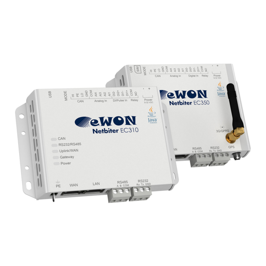
- Page 1 Netbiter EC300 Series USER MANUAL SCM-1202-012 2.2 ENGLISH...
- Page 2 Important User Information Liability Every care has been taken in the preparation of this document. Please inform HMS Industrial Networks AB of any inaccuracies or omissions. The data and illustrations found in this document are not binding. We, HMS Industrial Networks AB, reserve the right to modify our products in line with our policy of continuous product development.
-
Page 3: Table Of Contents
Table of Contents Page Preface ..........................3 About This Document.....................3 Document history......................3 Document Conventions ....................4 Installation ........................5 Basic Installation Steps ....................5 Factory Reset ........................5 Connectors........................6 LED Indicators ......................11 MODE Button ......................12 Wiring Examples......................13 Local Configuration...................... 14 Connecting via USB .....................14 Connecting via Ethernet ....................14 Login ..........................14 Status .........................15... - Page 4 This page intentionally left blank...
-
Page 5: Preface
Preface 3 (26) Preface About This Document This manual describes how to install and configure Netbiter EC300 Series gateways. For additional documentation and software downloads, FAQs, troubleshooting guides and tech- nical support, please visit www.netbiter.com/support. Document history Version Date Description 2016-10-03 First release with new layout 2017-10-07... -
Page 6: Document Conventions
This is a cross-reference within this document: Document Conventions, p. 4 This is an external link (URL): www.hms-networks.com This is additional information which may facilitate installation and/or operation. This instruction must be followed to avoid a risk of reduced functionality and/or damage to the equipment, or to avoid a network security risk. -
Page 7: Installation
Installation 5 (26) Installation Basic Installation Steps This product contains parts that can be damaged by electrostatic discharge (ESD). Use ESD protective measures to avoid equipment damage. Connecting power with reverse polarity or using the wrong type of power supply may damage the equipment. -
Page 8: Connectors
Installation 6 (26) Connectors 2.3.1 I/O Terminal Block Fig. 2 Terminal block Pin Label Function Note 15 HI CAN High 14 PE CAN Shield J1939 13 LO CAN Low 12 GND CAN Ground 11 COM Analog Input common 10 AI4 Analog Input 4 0–20 mA or 0–10 VDC Analog Input 3... - Page 9 Installation 7 (26) 2.3.2 Power Supply Connecting power with reverse polarity or using the wrong type of power supply may damage the equipment. Make sure that the power supply is correctly connected and of the recommended type. Fig. 3 Power supply connector Connect a DC power supply of the recommended type to the + (plus) - (minus) terminals.
- Page 10 Installation 8 (26) 2.3.4 SIM Card (EC350) Fig. 5 Installing the SIM card The SIM card must have a mobile data plan and allow text messaging. PIN code security must be disabled. Additional configuration in Netbiter Argos or in the local web interface is required. Insert the SIM card carefully and push it firmly downwards until it clicks into place.
- Page 11 Installation 9 (26) 2.3.6 RS-485 Serial Interface (3-pin) Fig. 7 RS-485 connector The RS-485 interface can be used for multiple Modbus RTU devices. RS-485 connector pin layout Function RS-485 A line RS-485 B line RS-485 common 2.3.7 RS-232 Serial Interface (3-pin) Fig.
- Page 12 Installation 10 (26) 2.3.8 Ethernet Ports (RJ45) Fig. 9 Ethernet Ports Use for Internet and Netbiter Argos Use for EtherNet/IP, Modbus TCP and Remote Access Never connect the LAN and WAN ports to the same logical network. RJ45 pin layout Function 4, 5, 7, 8 (reserved)
-
Page 13: Led Indicators
Installation 11 (26) LED Indicators All indicators will light up while the unit is starting up. When the startup sequence has completed they will indicate system status. In case of an Uplink/WAN error, check the network and firewall settings. If using DHCP, also check that the DHCP server is active. -
Page 14: Mode Button
Installation 12 (26) MODE Button Fig. 11 Mode button Factory Reset Keep the MODE button pressed while powering on to reset the unit to the factory default settings. Mobile Signal Strength Indication (EC350) Fig. 12 Press and release the MODE button to make the top 5 LED indicators indicate mobile signal strength for 60 seconds. -
Page 15: Wiring Examples
Installation 13 (26) Wiring Examples Fig. 13 Analog Input – Voltage Sensor Fig. 14 Analog Input – 2-wire Current Sensor Fig. 15 Analog Input – 3-wire Current Sensor Fig. 16 Analog Input – 4-wire Current Sensor Fig. 17 Analog Input – Temperature Sensor Fig. -
Page 16: Local Configuration
Local Configuration 14 (26) Local Configuration Local configuration is normally not required and should only be carried out when necessary. Please read the instructions below carefully. The built-in web interface is primarily intended for informational purposes and troubleshooting. Netbiter Argos is always the preferred way of configuring the gateway. The only configuration changes that should be made using the local web interface are: •... -
Page 17: Status
Local Configuration 15 (26) Status The Status tabs present an overview of the configuration as well as detailed information about the current connections, which can be used when troubleshooting and when contacting Netbiter support. Fig. 22 Status – Overview 3.4.1 Status –... - Page 18 Local Configuration 16 (26) 3.4.3 Status – Modem Fig. 25 Modem Status The Modem status tab presents basic and advanced information about the current mobile net- work connection. Basic information Data Connection Indicates if data connection is established Signal strength The strength of the mobile signal Network Mobile network operator...
-
Page 19: Network Settings - Wan
Local Configuration 17 (26) Network Settings – WAN Fig. 26 WAN settings The WAN interface should be enabled when connecting to Netbiter Argos via Ethernet. When DHCP is enabled the unit will automatically receive the settings for IP address, subnet mask, default gateway, and DNS. -
Page 20: Network Settings - Lan
Local Configuration 18 (26) Network Settings – LAN The LAN interface must be enabled when using EtherNet/IP or Modbus TCP applications and when using the Netbiter Remote Access service. These settings can also be made in Netbiter Argos. See the Netbiter Argos documentation. Fig. -
Page 21: Firmware Update
Local Configuration 19 (26) Firmware Update Firmware updates can also be made through Netbiter Argos. See the Netbiter Argos documentation. Fig. 29 Firmware update The Netbiter gateway must be connected to the Internet to ensure that the internal clock has synchronized the time and date before updating the firmware. Download the latest firmware from www.netbiter.com/support. -
Page 22: Modem Settings (Ec350)
Local Configuration 20 (26) Modem Settings (EC350) Modem settings and information about the mobile connection. These settings can also be made in Netbiter Argos. A SIM card with SMS capability is required. See the Netbiter Argos documentation. Fig. 30 Modem settings (EC350) Use modem as primary When enabled, mobile networking will be used as default as long as the signal connection to Argos... -
Page 23: A Ethernet/Ip Implementation
Appendix A: EtherNet/IP Implementation 21 (26) EtherNet/IP Implementation See also the Netbiter Argos documentation on how to configure EtherNet/IP. Client Connection Type UCMM (Class 1 and 3 connection not supported) Adapter Timeout 1000 ms Services The following services are implemented: Code Service Name Addressing... - Page 24 Appendix A: EtherNet/IP Implementation 22 (26) A.2.2 TCP/IP Interface Object (0xF5) Class Attributes The following class attributes are implemented: Access Name Revision Instances Instance 1 is implemented with the following attributes: Access Name Status Configuration Capability Configuration Control Physical Link Object Interface Configuration Hostname Get/Set...
-
Page 25: B Technical Data
Appendix B: Technical Data 23 (26) Technical Data Technical Specifications Product name Netbiter EC310 Netbiter EC320, EC350 Model name NB301B NB301A Order code NB1007-C EC320: NB1021 EC350: NB1005-C EC350 (no antenna): NB1008-C – Mobile communication Quad-band GSM/GPRS: 850, 900, 1800, 1900 MHz EC350 only: 5-band 3G + GSM/GPRS –... -
Page 26: Installation Drawings
Appendix B: Technical Data 24 (26) Installation Drawings Dimensions (EC350) All measurements are in millimeters. Fig. 31 EC350 dimensions Netbiter EC300 Series User Manual SCM-1202-012 2.2... - Page 27 This page intentionally left blank...
- Page 28 © 2017 HMS Industrial Networks AB Box 4126 300 04 Halmstad, Sweden info@hms.se SCM-1202-012 2.2.6116 / 2017-11-13...
Need help?
Do you have a question about the eWON Netbiter EC300 Series and is the answer not in the manual?
Questions and answers