
Subscribe to Our Youtube Channel
Related Manuals for HMS Anybus HMS-EN2MB-R


Summary of Contents for HMS Anybus HMS-EN2MB-R
- Page 1 Linking Device EtherNet/IP to Modbus-TCP USER MANUAL scm-1202–181 2.0 en-US ENGLISH...
- Page 2 HMS Networks reserves the right to modify its products in line with its policy of continuous product development. The information in this document shall therefore not be construed as a commitment on the part of HMS Networks and is subject to change without notice. HMS Networks makes no commitment to update or keep current the information in this document.
-
Page 3: Table Of Contents
Table of Contents Page Preface ..........................5 About This Document .......................5 Document Conventions .....................5 Related Documents ......................5 Document History ......................6 Trademarks........................6 About the Linking Device....................7 Features .........................7 Data Consistency......................7 Installation........................... 9 External View ........................9 Mounting the Linking Device....................9 Power Connector ......................11 EtherNet/IP &... - Page 4 Data Transactions......................33 I/O Mapped Data ......................33 Parameter Data ......................33 Control/Status Word....................... 33 Live List ........................33 Transaction Status List ....................34 Exception Code List ......................35 Modbus-TCP Functions ..................... 37 Linking Device Configuration Manager Interface ............38 Menu Options .......................
- Page 5 H Copyright Notices ......................67 scm-1202–181 2.0 en-US Linking Device User Manual...
- Page 6 This page intentionally left blank...
-
Page 7: Preface
Preface 5 (70) Preface About This Document This document describes how to install and configure the HMS-EN2MB-R EtherNet/IP to Modbus-TCP linking device. For related documentation and file download, visit the support website at www.anybus.com/support. Document Conventions Numbered lists indicate tasks that should be carried out in sequence:... -
Page 8: Document History
This document replaces SCM-1202–008. Trademarks ® ™ Anybus is a registered trademark and HMS-EN2MB-R is a trademark of HMS Networks AB. All other trademarks mentioned in this document are the property of their respective holders. scm-1202–181 2.0 en-US Linking Device User Manual... -
Page 9: About The Linking Device
About the Linking Device 7 (70) About the Linking Device Features The EtherNet/IP to Modbus-TCP linking device provides a seamless connection between an Allen- Bradley Programmable Controller (PLC) by Rockwell Automation on EtherNet/IP and a Modbus- TCP network. It features: •... - Page 10 About the Linking Device 8 (70) Each of the two network interfaces exchanges data on its network through two buffers. The linking device forwards the data internally between these buffers as shown below. Status Word Data To Data From the Modbus-TCP the Modbus-TCP Network Network...
-
Page 11: Installation
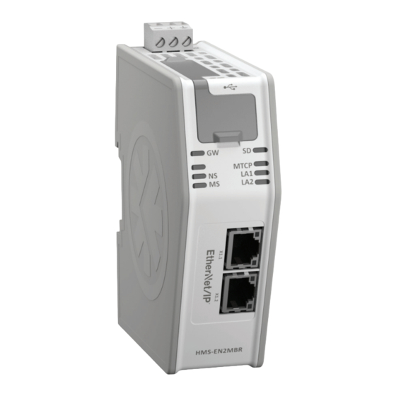
Installation 9 (70) Installation External View Use the SD card slot with care. Do not use an SD card for configuration backups. A backup of the configuration is always stored in the Studio 5000 project. The configuration in the linking device and in Studio 5000 must match for operation. See SD Card Functionality, p. - Page 12 Installation 10 (70) 3.2.1 DIN-rail Mounting Make sure the DIN-rail fastening mechanism on the back of the module is in a fixed and closed position, i. e. pushed all the way up. To mount the module, first hook it on to the DIN-rail (1), then push it against the DIN-rail to make it snap on (2).
-
Page 13: Power Connector
Installation 11 (70) Step Description Visual Description Open up the package containing the wall mounting accessories. - One metal frame - Industrial velcro - Four plastic vibration dampers Remove the plastic protection from one side of the velcro. Attach the velcro to the metal frame. Attach the four plastic vibration dampers to the linking device, on the side that will face the wall. -
Page 14: Ethernet/Ip & Modbus-Tcp Rj45 Connectors
Installation 12 (70) EtherNet/IP & Modbus-TCP RJ45 Connectors Pin no Description Connector 4, 5, 7, 8 Not connected Housing Shield USB Connector Connector Pin no Description +5 V Input USBDM (USB communication signals) USBDP (USB communication signals) Signal GND Housing Cable shield scm-1202–181 2.0 en-US Linking Device User Manual... -
Page 15: Configuration
Modbus-TCP client configuration manager is closed. The next time the configuration manager is opened, the stored configuration is retrieved. The linking device is configured in the following basic steps: In Studio 5000, set up and launch the HMS-EN2MB-R configuration manager (step 1–6 in Studio 5000 Configuration Example, p. 15). -
Page 16: Modbus-Tcp Client Configuration
Configuration 14 (70) linking device is online or offline. The linking device configuration cannot be changed when the connection is online. Linking Device Configuration Manager Interface, p. 38 for a description of the menu options. Modbus-TCP Client Configuration The EtherNet/IP to Modbus-TCP linking device has a built-in Modbus—TCP client configuration manager. -
Page 17: Studio 5000 Configuration Example
Configuration 15 (70) • Transactions will be added to connections in the order they are created in the Modbus configuration manager. If a transaction does not fit into the remaining parts of a connection, it will be moved to the next connection. - Page 18 Configuration 16 (70) Select the EtherNet/IP to Modbus-TCP linking device (catalogue number: HMS-EN2MB-R) and click Create. In the New Module window, assign a name to the module. The IP address should be set via the BOOTP-DHCP server and entered in the IP address field.
- Page 19 Configuration 17 (70) In the Module Definition window, launch the configuration manager for the HMS-EN2MB-R linking device by clicking the View and edit the network button. scm-1202–181 2.0 en-US Linking Device User Manual...
- Page 20 The first step is to configure the Modbus-TCP Client to define the process data to be sent through the linking device. The HMS-EN2MB-R uses a built in web interface in the actual linking device to configure the Modbus-TCP Client.
- Page 21 Configuration 19 (70) The first view in the Modbus-TCP Client interface is the overview. The overview presents a summary of useful information about the linking device. Select Modbus Servers in the left-hand menu to add Modbus-TCP servers to the configuration. Click Add new server to add the configuration for a new Modbus-TCP server.
- Page 22 Configuration 20 (70) 10. Perform the following steps to add and configure a new transaction: Click Add new transaction and select Edit. Add a name of the transaction in the Name field in General transaction settings. “MyTrans1” is used in this example. Select the Modbus command function that should be executed.
- Page 23 Configuration 21 (70) 11. If you want to add another transaction, repeat the procedure in the previous step (step 10). Modbus-TCP Functions, p. 37 for information about supported Modbus-TCP functions. This example defines another transaction named “MyTrans2” that uses function code 16 (Write Multiple Registers) and writes 20 elements (40 bytes).
- Page 24 Configuration 22 (70) 13. When the configuration of servers and transactions is complete, select HMS-EN2MB-R Management under Tools in the left-hand menu. Click Apply in the Apply changes section to download the configuration to the linking device. The configuration will now be verified.
- Page 25 Configuration 23 (70) 14. Close the Modbus-TCP Client configuration manager to show the tag editor in the Linking Device configuration manager again. The tag editor will generate tags based on the Modbus-TCP Client configuration and how the process data is placed in the assemblies. All new tags have a Tag Names are marked in magenta.
- Page 26 Configuration 24 (70) 15. When the configuration is finished, close the tag editor window. The tag configuration, a checksum and the current project configuration files are sent to Studio 5000. The tag configuration is used in the Studio 5000 project to create signals and automatically map them to the linking device.
-
Page 27: Tag Editor Configuration
Configuration 25 (70) 16. Right-click the computer icon and select Download to download the configuration from Studio 5000 to the PLC. Tag Editor Configuration The tag editor will generate tags when the Modbus-TCP Client configuration manager has been edited and is closed. The tags will be based on the Modbus-TCP Client configuration and how the process data have been placed in the assemblies. - Page 28 Configuration 26 (70) unchecked tags will still be available in the process data, but no tag will be created in Studio 5000. You can make mass operations on all tags by right-clicking on a Modbus-TCP server or transaction in the tree structure to the left. Tag Editor Options, p.
- Page 29 Configuration 27 (70) To create an array tag, set a positive value in the dimension field. The tag editor will automatically allocate the following number of tags of that value and mark them blue. The tags are now uneditable. The name of the first tag will be used as the name of the array tag. Original names of the tags collected in the array will be remembered by the tag editor.
- Page 30 Configuration 28 (70) You can collapse array tags into single lines to get a more compact overview of the configuration. Check the Collapse arrays checkbox under the tag list view. 4.6.2 Tag Rule Definitions The default and automatically generated tags will adhere to the rules below. All process tags (controller tags) in the configuration must follow these rules: •...
-
Page 31: Verify Operation
Verify Operation 29 (70) Verify Operation Status LEDs A test sequence is performed on all LEDs during startup. At power up, LED 1 - 2 will indicate solid orange and LED 3 - 4 will indicate solid yellow for 15 - 30 seconds. -
Page 32: Maintenance
Maintenance 30 (70) Maintenance EMC (CE) Compliance EMC compliance testing has been conducted according to the Electromagnetic Compatibility Directive 2004/108/EC. For more information please consult the EMC compliance document, see product/support pages for EtherNet/IP to Modbus-TCP Linking Device at www.anybus.com. Replace a Linking Device The recommended procedure to back up a configuration is to use the backup function in Studio 5000. - Page 33 Maintenance 31 (70) • Replacement Replace a Linking Device, p. 30 for the recommended linking device replacement procedure. If a linking device malfunctions during operation, a replacement device can be configured by moving the SD card to the new device. A configuration on the linking device is saved automatically to the SD card in any of these two events: •...
- Page 34 This page intentionally left blank...
-
Page 35: A Data Transactions
Appendix A: Data Transactions 33 (70) Data Transactions I/O Mapped Data I/O mapped data is cyclic data, exchanged between the networks and/or devices at a high transfer rate. It’s associated with implicit messaging, where data is continuously sent on the network. -
Page 36: Transaction Status List
Appendix A: Data Transactions 34 (70) The live list is always accessible to the PLC on the EtherNet/IP network using acyclic parameter access. By default, the live list is also mapped as the first eight bytes after the status word (if enabled) to the cyclic process data in the direction from the linking device to the PLC. -
Page 37: Exception Code List
Appendix A: Data Transactions 35 (70) The transaction status list is always accessible to the PLC on the EtherNet/IP network using acyclic parameter access. The transaction status list contains a byte array with 64 elements. Each byte contains a transaction status code according to the table below. The indexes in the transaction status list correspond completely to the indexes in the transaction live list. - Page 38 Appendix A: Data Transactions 36 (70) Standard Modbus Exception Codes (continued) Exception Code Description Memory parity error Gateway path unavailable Gateway target device failed to respond The exception codes found in the exception code list are only relevant if the corresponding transaction status codes equals 3: “Modbus exception”.
-
Page 39: B Modbus-Tcp Functions
Appendix B: Modbus-TCP Functions 37 (70) Modbus-TCP Functions The Modbus-TCP protocol is an implementation of the standard Modbus protocol, running on top of TCP/IP. The same function codes and addressing model are used. The EtherNet/IP to Modbus-TCP linking device supports a subset of the functions described in the Modbus-TCP specification. -
Page 40: C Linking Device Configuration Manager Interface
Appendix C: Linking Device Configuration Manager Interface 38 (70) Linking Device Configuration Manager Interface Menu Options Import File Imports a configuration. Export Exports a configuration. Exit Edit Select All Deselect All Tools Edit Modbus Configuration Launches the Modbus-TCP Master user interface. Launch IPconfig Scans for devices and configure IP settings for the linking device. -
Page 41: D Modbus-Tcp Client Configuration Manager
Modbus-TCP Client Configuration Manager The Modbus configuration and status pages are divided into three sections. Headline Section Shows the HMS logo and the name of the product. Navigation Section All functionality is easily accessed from the different links. Every link and its corresponding functionality will be explained later in this chapter. -
Page 42: Home
Appendix D: Modbus-TCP Client Configuration Manager 40 (70) Home The introductory window of the configuration and status pages presents important error tracking information, as well as general information and statistics. D.1.1 Operation Mode The table below shows the correlation between the operation modes of the Modbus-TCP network and the EtherNet/IP network. - Page 43 Appendix D: Modbus-TCP Client Configuration Manager 41 (70) Authentication can be enabled or disabled. If enabled, you can set a username and password to protect the configuration. When choosing a username and a password, use only the valid characters shown below. Item Valid characters Username...
- Page 44 Appendix D: Modbus-TCP Client Configuration Manager 42 (70) IP Configuration Settings (continued) Description Item Subnet mask Router IP address DHCP Enabled by default. When enabled, the linking device can obtain the TCP/IP settings dynamically from the DHCP server of the Modbus-TCP network. Start-up Operation Mode Description Value...
- Page 45 Appendix D: Modbus-TCP Client Configuration Manager 43 (70) Server Settings Setting Description Name While not required, renaming the server makes the configuration easier to comprehend. Note that it is only possible to use uppercase and lowercase characters, numerals and underscore (_). Default name is ‘New_Server’, followed by an incremental suffix.
- Page 46 Appendix D: Modbus-TCP Client Configuration Manager 44 (70) The linking device needs to be restarted before any changes will take effect. Transaction Settings Setting Description Function code The function code defines the purpose of the transaction. Choose from the available different Modbus functions. Data encoding Decides in what order the different bytes of the received/transmitted data shall be sent on the Modbus network.
- Page 47 Appendix D: Modbus-TCP Client Configuration Manager 45 (70) Transaction Settings (continued) Setting Description The minimum scan time will increase by adding more transactions. Value range: 10 - 10000 (ms). Unit ID Only applicable for Modbus RTU servers. If the Modbus-TCP server work as a router to Modbus RTU servers, it is possible to send transactions to a single Modbus RTU server using the unit ID.
-
Page 48: Tools
If enabled, the live list is mapped to the input area. Tools D.3.1 HMS EN2MB-R Management Apply Changes Permanently store changes made to the configuration and reboot, using the new configuration. No changes made in the configuration will be permanently stored or used by the linking device until they are applied by clicking “Apply”. - Page 49 Appendix D: Modbus-TCP Client Configuration Manager 47 (70) Two things can happen when loading an old configuration: • Configuration valid: The linking device will reboot and automatically use the previously stored configuration. • Configuration not valid: The linking device will produce an error message. The chosen configuration will not be accepted or loaded into memory.
- Page 50 Appendix D: Modbus-TCP Client Configuration Manager 48 (70) D.3.4 Transaction Monitor The transaction monitor interface presents a detailed list of all transactions currently operating on the Modbus-TCP network. To start or stop the transaction monitor, press the desired button. The data in the transaction monitor is automatically updated, and it is possible to choose to view the data either in decimal or in hexadecimal values.
-
Page 51: Ecip Objects
Get_Attributes_All Reset Class Attributes Name Access Type Value Revision UINT 0001h (Object revision) Instance Attributes Name Access Type Value/Description UINT Vendor ID 005Ah (HMS Industrial Networks AB) Device Type UINT 000Ch (Communications Adapter) scm-1202–181 2.0 en-US Linking Device User Manual... - Page 52 Struct of: Major and minor firmware revision USINT USINT Status WORD See Device Status table below Serial Number UDINT Unique serial number (assigned by HMS) Product Name SHORT_STRING “EtherNet/IP to Modbus-TCP Linking Device” Active Struct of: Only English supported. language USINT...
-
Page 53: Message Router (02H)
The Message Router Object provides a messaging connection point through which a client may address a service to any object class or instance residing in the physical module. In the HMS-EN2MB-R module it is used internally to direct object requests. Supported Services... -
Page 54: Assembly Object (04H)
Appendix E: CIP Objects 52 (70) Class Attributes Instance Attributes Assembly Object (04h) Category Extended Object Description The Assembly object uses static assemblies and holds the Process Data sent/received by the host application. It allows data to and from each object to be sent or received over a single connection. The default assembly instance IDs used are 100-109 and 150-159. - Page 55 Appendix E: CIP Objects 53 (70) Name Access Type Value/Description Data - (The data size of this attribute is zero) Size UINT 0 (Number of bytes in attribute 3) Instance 05h Attributes (Configuration Data) Configuration Data that is sent through the service Forward_Open will be written to this instance. Name Access Type...
-
Page 56: Connection Manager (06H)
Appendix E: CIP Objects 54 (70) Connection Manager (06h) Category Extended Object Description Supported Services Class: Instance: Forward_Open Forward_Close Class Attributes (No supported class attributes) Instance Attributes (No supported instance attributes.) Class 0 Connection Details Not supported. Class 1 Connection Details General Class 1 connections are used to transfer I/O data, and can be established to instances in the Assembly Object. - Page 57 Appendix E: CIP Objects 55 (70) Connection Types • Exclusive-Owner connection This type of connection controls the outputs of the HMS-EN2MB-R and does not depend on other connections. Max. no. of Exclusive-Owner connections: Connection point O →T: Assembly Object, instance 64h (Default) Connection point T →O:...
-
Page 58: Dlr Object (47H)
Appendix E: CIP Objects 56 (70) Class 3 Connection Details General Class 3 connections are used to establish connections towards the message router. Thereafter, the connection is used for explicit messaging. Class 3 connections use TCP transport. No. of simultaneous Class 3 connections: 16 2... -
Page 59: Qos Object (48H)
Appendix E: CIP Objects 57 (70) Name Access Type Value/Description Active Struct of: UDINT This attribute holds the IP address (IPv4) and/or the Ethernet Supervisor Mac address of the active ring supervisor. Array of: Address 6 USINTs Capability Flags Get DWORD 01h (Announce-based ring node) QoS Object (48h) -
Page 60: Port Object (F4H)
Appendix E: CIP Objects 58 (70) Supported Services Class: Get_Attribute_Single Instance: Get_Attribute_Single Set_Attribute_Single Class Attributes Name Access Type Value Revision UINT 0001h (Object revision) Instance Attributes Each instance corresponds to an instance within the Application Data Object. Name Access Type Description Name SHORT_STRING... -
Page 61: Tcp/Ip Interface Object (F5H)
Appendix E: CIP Objects 59 (70) Name Access Type Value Entry Port UINT Returns the instance of the Port Object that describes the port through which this request entered the device Port Instance Array of: Array of structures containing instance attributes 1 and 2 from Info each instance. - Page 62 Default gateway Primary DNS UDINT (DNS1) UDINT (DNS2) Secondary DNS STRING Default domain (Domain) Host Name STRING Host name of the HMS-EN2MB-R Get/Set TTL Value USINT Get/Set TTL value for EtherNet/IP multicast packets Mcast Config Struct of: IP multicast configuration...
-
Page 63: Ethernet Link Object (F6H)
Appendix E: CIP Objects 61 (70) Name Access Type Value Comments Enable ACD (Default). If ACD (address conflict detection) is enabled, bit 6 in attribute #1 will be set if an ACD conflict is detected. The Network Status LED will also indicate a detected conflict. - Page 64 Appendix E: CIP Objects 62 (70) Name Access Type Value Comments scm-1202–181 2.0 en-US Linking Device User Manual...
- Page 65 Appendix E: CIP Objects 63 (70) Name Access Type Value Comments Interface Struct of: Get/Set Control WORD Control Bits Interface control bits UINT Forced Speed at which the interface shall be Interface forced to operate. Returns ‘Object state Speed Conflict’ if auto-negotiation is enabled USINT Interface Type See table “Interface Type”...
-
Page 66: F Technical Specification
DIN-rail connector. If the DIN-rail cannot be used, FE must be connected to the power connector. HMS Networks AB does not guarantee proper EMC behavior unless these FE requirements are fulfilled. Make sure the DIN-rail is properly connected to FE. -
Page 67: Gsd Card Functionality
Appendix G: SD Card Functionality 65 (70) SD Card Functionality The recommended procedure to back up a configuration is to use the backup function in Studio 5000. It is NOT recommended to use the SD card for backups. The SD card acts as client in the linking device. When a device is turned on with an SD card inserted, and that SD card contains a valid configuration file, the configuration on the SD card will always overwrite any configuration on the linking device. -
Page 68: Sd Card Synchronization Failure
Appendix G: SD Card Functionality 66 (70) Remove the SD card from the linking device containing the desired configuration and insert it into another one. The firmware version must be the same or higher in the new linking device. The new linking device must support the same network type as the first linking device. Turn the new linking device on. - Page 69 Appendix H: Copyright Notices 67 (70) Copyright Notices This product includes software developed by Carnegie Mellon, the Massachusetts Institute of Technology, the University of California, and RSA Data Security: ***************************************************************************** Copyright 1986 by Carnegie Mellon. ***************************************************************************** Copyright 1983,1984,1985 by the Massachusetts Institute of Technology ***************************************************************************** Copyright (c) 1988 Stephen Deering.
- Page 70 Appendix H: Copyright Notices 68 (70) RSA Data Security, Inc. makes no representations concerning either the merchantability of this software or the suitability of this software for any particular purpose. It is provided "as is" without express or implied warranty of any kind. These notices must be retained in any copies of any part of this documentation and/or software.
- Page 71 This page intentionally left blank...
- Page 72 © 2021 HMS Industrial Networks Box 4126 300 04 Halmstad, Sweden info@hms.se scm-1202–181 2.0 en-US / 2021-05-19 / 22485...
Need help?
Do you have a question about the Anybus HMS-EN2MB-R and is the answer not in the manual?
Questions and answers