Table of Contents
Advertisement
Quick Links
Advertisement
Table of Contents

Related Manuals for IFM PM11


Summary of Contents for IFM PM11
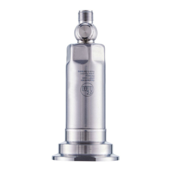
- Page 1 Operating instructions Electronic pressure sensor PM11...
-
Page 2: Table Of Contents
PM11 Electronic pressure sensor Contents Preliminary note ............. -
Page 3: Preliminary Note
Electronic pressure sensor PM11 1 Preliminary note You will find instructions, technical data, approvals and further information using the QR code on the unit / packaging or at www.ifm.com. 1.1 Symbols used Requirement Instructions Reaction, result [...] Designation of keys, buttons or indications... -
Page 4: Safety Instructions
PM11 Electronic pressure sensor 2 Safety instructions • The unit described is a subcomponent for integration into a system. – The system architect is responsible for the safety of the system. – The system architect undertakes to perform a risk assessment and to create documentation in accordance with legal and normative requirements to be provided to the operator and user of the system. -
Page 5: Intended Use
Electronic pressure sensor PM11 3 Intended use The unit measures and monitors the system pressure of machines and installations. Two outputs are available: OUT1: Measured pressure value via IO-Link. OUT2: Analogue signal proportional to pressure 4...20 mA. 3.1 Application area Type of pressure: relative pressure Information on pressure rating and bursting pressure Ò... -
Page 6: Function
PM11 Electronic pressure sensor 4 Function Measuring cell: • The system pressure is measured by a ceramic capacitive measuring system. • The sealing of the ceramic measuring cell is free of elastomers and thus maintenance-free. Signal transmission: • The unit can be operated in analogue mode and in IO-Link mode. When connected to an IO-Link master, the unit automatically switches to IO-Link mode. -
Page 7: Defined State In Case Of A Fault
• Location Tag: freely definable text describing the installation location in the plant. For more detailed information refer to the device-specific IO Device Description PDF at www.ifm.com. 4.3 Defined state in case of a fault If a fault is detected, the analogue output passes into a defined state ( = 21.5 mA). - Page 8 PM11 Electronic pressure sensor [mA] 21,5 20,5 [% MEW] -1,25 100 103,13 Fig. 1: Output characteristics of the analogue output to Namur Analogue signal Measured value Measuring range Scaled measuring range Signalling fault 21.5 mA Pressure MAW: Initial value of the measuring range with non-scaled measuring range.
-
Page 9: Installation
Electronic pressure sensor PM11 5 Installation The device can be adapted to clamp connections 1“ – 1.5“ [DIN 32676 (ISO 2852)]. Before installing and removing the device: Make sure that no pressure is applied to the system and there is no medium in the pipe. -
Page 10: Use In Hygienic Areas According To 3-A
PM11 Electronic pressure sensor 5.1 Use in hygienic areas according to 3-A The following applies to devices with 3-A certification: u Only use adapters with 3-A certification for the process connection. u Do not install the device in the lower section of the pipe or tank (positions 4 and 5) in order that the medium can run off the area of the measuring element. -
Page 11: Orientation Filter Cover
Electronic pressure sensor PM11 For a correct functioning of the ventilation diaphragm please take the following into account: u Remove soiling and cleaning agents immediately using plenty of lime-deficient splash water. If the sensor is in a cooling stage: u Avoid contact of the ventilation diaphragm with liquids to avoid negative pressure in the measuring system (resulting in a slightly falsified measured value) and additional strain on the diaphragm. - Page 12 PM11 Electronic pressure sensor u Avoid soiling and moisture during the exchange u Clean the thread carefully and without residues. u Do not damage the adhesive surface for the diaphragm on the sensor. u Observe the orientation of the filter cover (Ò Installation instructions E30139 / E30467).
-
Page 13: Electrical Connection
Electronic pressure sensor PM11 6 Electrical connection The unit must be connected by a qualified electrician. Observe the national and international regulations for the installation of electrical equipment. Voltage supply according to SELV, PELV. u Disconnect power. u Connect the unit as follows:... -
Page 14: Parameter Setting
Put the device into operation. 7.2 Parameter setting via the memory plug A parameter set can be written to the device / can be recorded by the device via a memory plug (ifm storage module): www.ifm.com. In order to allow for data to be written from the memory plug to the sensor, the sensor must have the factory setting. -
Page 15: Teach Offset With Button
Electronic pressure sensor PM11 7.3 Teach offset with button An external teach button (E30425) allows for a zero-point calibration (calibration offset). The current measured value is taken as internal zero point if this measured value lies within a range of +/- 3% of the measuring span. -
Page 16: List Of The Parameters
PM11 Electronic pressure sensor 7.7 List of the parameters Parameter Function ASP2 Analogue start point: Measured value at which 4 mA is provided. AEP2 Analogue end point: Measured value at which 20 mA is provided. Minimum distance between ASP and AEP = 20% of the measuring span. -
Page 17: Operation
Electronic pressure sensor PM11 8 Operation After power-on and expiry of the power-on delay time of approx. 0.5 s the unit is in the RUN mode (= normal operating mode). It carries out its measurement and evaluation functions and generates output... -
Page 18: Troubleshooting
It monitors itself automatically during operation. Warnings and faults are signalled via IO-Link. If a process value fails, the other process values are still available. Additional diagnostic functions are available via IO-Link. IODD interface description at: www.ifm.com. The IO-Link error codes are contained in the IODD. Type... -
Page 19: Disposal, Repair And Return
Electronic pressure sensor PM11 10 Disposal, repair and return u In case of return shipment, ensure that the unit is free from soiling, especially from dangerous and toxic substances. u It is not possible to repair the unit. u After use dispose of the product or components in an environmentally friendly way in accordance... -
Page 20: Factory Setting
PM11 Electronic pressure sensor 11 Factory setting Factory setting User settings ASP2 0% VMR* AEP2 100% VMR bar / mbar 0.06 VMR = final value of the measuring range *= the indicated percentage of the final value of the measuring range (VMR) of the corresponding...
Need help?
Do you have a question about the PM11 and is the answer not in the manual?
Questions and answers