
Related Manuals for DITEC OBBI


Summary of Contents for DITEC OBBI
- Page 1 Last version of this manual IP1639EN•2023-05-12 Ditec OBBI Technical Manual Swing gates automation (translation of the original instructions) www.ditecautomations.com...
-
Page 2: Table Of Contents
Index General safety precautions .......................... 25 Declaration of incorporation of partly completed machinery .................. 26 UK Declaration of Conformity .......................... 27 Technical specifications .......................... 28 Operating instructions ..........................29 Machinery Directive ..........................29 Standard installation .......................... 30 Geared motor references .......................... -
Page 3: General Safety Precautions
General safety precautions ATTENTION! Important safety instructions.Please follow these instructions carefully. Failure to observe the information given in this manual may lead to severe personal injury or damage to the equipment.Keep these instructions for future reference. This manual and those for any accessories can be downloaded from www.ditecautomations.com This installation manual is intended for qualified personnel only •... -
Page 4: Declaration Of Incorporation Of Partly Completed Machinery
SE-261 44 Landskrona Sweden, declare, under our sole responsibility, that the type of equipment with the name: Ditec OBBI Automation for swing gates complies with the following directives and their amendments: 2006/42/EC Machinery Directive (MD), regarding the following essential health and safety requirements: 1.1.2, 1.1.3, 1.2.1, 1.2.2, 1.2.3, 1.2.4.2, 1.2.6, 1.3.9, 1.4.3, 1.7.2, 1.7.3, 1.7.4, 1.7.4.1, 1.7.4.2. -
Page 5: Declaration Of Conformity
Lodjursgatan 10 SE-261 44 Landskrona Sweden Declare under our sole responsibility that the types of equipment with names: Ditec OBBI Automation for swing gates complies with the following directives and their amendments: • Supply of Machinery (Safety) Regulations 2016 • Electromagnetic Compatibility Regulations 2016 •... -
Page 6: Technical Specifications
1. Technical specifications Ditec OBBI3BH Power supply 24 V= Absorption Thrust 1500 N Max run 350 mm Opening time 25 s / 90° Max. door weight 250 kg Max. door width 3,0 m 3 - FREQUENTE Service class (tested up to 150.000 cycles) S2= 30 min (T= 25°C) -
Page 7: Operating Instructions
1.1 Operating instructions Use: FREQUENT (for vehicle or pedestrian for single-family or multi-family with frequent use). - Performance characteristics are to be understood as referring to the recommended weight (ap- prox. 2/3 of maximum permissible weight). A reduction in performance is to be expected when the access is made to operate at the maximum permissible weight. -
Page 8: Standard Installation
2. Standard installation Ref. Code Description Cable Connector block (not supplied). Connect the power supply to an approved omnipolar switch with an opening distance of the contacts of at least 3mm (not supplied). The connection to the mains must be made via an independent channel, separated from the connections to command and safety devices. -
Page 9: Geared Motor References
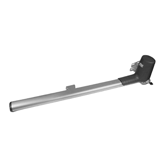
3. Geared motor references Ø8,5 Ø12 Ø12 Ref. Code Description Key release Casing Draft tube Tube cover Closing plug Tail bracket Head bracket Cable guide sheat hooking bracket... -
Page 10: Installation
4. Installation The given operating and performance features can only be guaranteed with the use of DITEC ac- cessories and safety devices. Unless otherwise specified, all measurements are expressed in mm. 4.1 Preliminary checks Check that the structure is sufficiently rugged and that the hinge pivots are properly lubricated. - Page 11 • If the gearmotor opening direction needs to be modified, proceed as shown in the figure (example of motor transformation with opening direction from right to left). blue brown • Loosen the motor fastening screws. • Extract the motor and the reducer cap and unthread the motor cable.
- Page 12 - Fix the tail bracket [14], respecting measurements [A] and [B] on the basis of the desired open- ing angle [D]. - On the tail bracket there are holes that facilitate the assembly operation. - Fix the piston to the rear bracket [14] with the pin [F] supplied. - Extend the haulage tube completely [11] to its maximum length, then shorten it by approximately 20 mm.
- Page 13 - Assemble the tube cover [12] with the cap [13] and seal, and fix it with the screws [H] supplied. Pay attention to the insertion direction. The slits on the closing cap [13] must be on the lower part in order to help the water to come out. - Assemble the casing [10], fixing it with the screw [N], paying attention to the positioning of the cable.
-
Page 14: Electrical Connections
5. Electrical connections Before connecting the power supply, make sure the plate data correspond to that of the mains power supply. An omnipolar disconnection switch with minimum contact gaps of 3 mm must be included in the mains supply. Check that upstream of the electrical installation there is an adequate residual current circuit breaker and a suitable overcurrent cutout. -
Page 15: Routine Maintenance Plan
6. Routine maintenance plan Perform the following operations and checks every 6 months according to intensity of use of the automation. Disconnect the 230 V~ power supply and batteries if present: - Clean and lubricate, using neutral grease, the turning pins, the hinges of the gate and the drive screw. -
Page 16: Operating Instructions
Operating instructions General safety precautions for the user ATTENTION! Important safety in- structions • Please follow these instructions carefully • Failure to observe the information given in this manual may lead to severe personal injury or damage to the equipment • Keep these instruc- tions for future reference. - Page 17 1.5 m, and out of reach of the public • The motorized door or gate may be used by children over the age of 8 and by people with reduced physical, sensorial or mental abilities, or lack of experience or knowledge, as long as they are properly supervised or have been instructed in the safe use of the device and the relative hazards •...
-
Page 18: Manual Release Instructions
Manual release instructions In the event of a fault or blackout, release any electric lock, insert the key and turn RIGHT PISTON it anticlockwise (in the direction indicated by the arrow on the gearmotor). Manually open the gate. To block the door wings again, turn the key clockwise (in the opposite direc- tion to the arrow on the gearmotor). - Page 20 All the rights concerning this material are the exclusive property of ASSA ABLOY Entrance Systems AB. Although All the rights concerning this material are the exclusive property of ASSA ABLOY Entrance Systems AB. Although the contents of this publication have been drawn up with the greatest care, ASSA ABLOY Entrance Systems AB the contents of this publication have been drawn up with the greatest care, ASSA ABLOY Entrance Systems AB cannot be held responsible in any way for any damage caused by mistakes or omissions in this publication.
Need help?
Do you have a question about the OBBI and is the answer not in the manual?
Questions and answers