Table of Contents
Advertisement
Quick Links
Advertisement
Table of Contents

Subscribe to Our Youtube Channel
Related Manuals for AC Infinity AC-BFP4


Summary of Contents for AC Infinity AC-BFP4
- Page 1 AUTO BOOSTER FAN WITH PRESSURE SWITCH USER MANUAL USER MANUAL...
- Page 3 WELCOME Thank you for choosing AC Infinity. We are committed to product quality and friendly customer service. If you have any questions or suggestions, please don’t hesitate to contact us. Visit www.acinfinity.com and click contact for our contact information. EMAIL LOCATION support@acinfinity.com...
- Page 4 MANUAL CODE BFP2211X1 PRODUCT MODEL UPC-A Automatic Duct Booster Fan 4" AC-BFP4 819137023789...
-
Page 5: Table Of Contents
Page 11 Installation: Configuration Setup ............ Page 16 Powering and Setup ..............Page 17 Cleaning ..................Page 18 Programming ................. Page 20 Recalibration .................. Page 23 ....................Page 26 Other AC Infinity Products ............. Page 27 Warranty ..................Page 28... -
Page 6: Product Warning
PRODUCT WARNING TO REDUCE THE RISK OF FIRE, ELECTRIC SHOCK, OR INJURY TO PERSONS, OBSERVE THE FOLLOWING: Ensure your power source conforms to the electrical requirements of this product. Check your local code restrictions for additional safety measures that may be needed for a proper code compliant installation. - Page 7 PRODUCT WARNING MOVEMENT AFTER INSTALLATION Do NOT move the fan after it is fully installed. Movement of the fan unit may result in false triggers as a result of changing differential pressure and will require recalibration. See page 23 for recalibration steps. DIFFERENTIAL PRESSURE SWITCH The differential pressure switch has positive and negative outlets.
-
Page 8: Key Features
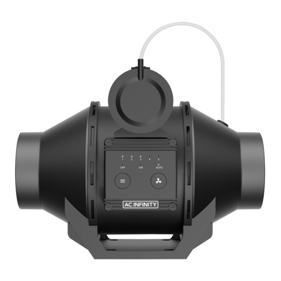
KEY FEATURES DIGITAL CONTROLLER DUAL BALL BEARINGS PRESSURE SENSITIVE 5-speed controller featuring The motor contains ball bearings Differential pressure-sensing OFF, ON, and AUTO Modes with an estimated 67,000 hour switch automatically activates for custom pressure triggering lifespan. Enables the fan to be the fan whenever positive and activation levels. -
Page 9: Product Contents
PRODUCT CONTENTS DUCT FAN WIRE PROBE WOOD SCREWS SYSTEM MOUNT MOUNT (WALL HANG) (x1) (x6) (x1) (x4) - Page 10 PRODUCT CONTENTS...
-
Page 11: Installation: Mounting
INSTALLATION MOUNTING STEP 1 Remove the tube from the differential pressure switch. Unscrew the bolts on both sides from the plastic rings using a Phillips screwdriver. STEP 2 Remove the motor box from the flange bracket. Remove the wind circle between the motor box and the intake flange. - Page 12 INSTALLATION MOUNTING STEP 3 Use the flange bracket to set your desired fan position. Mark the four mounting holes. Your fan MUST be mounted at least 5 ft. away from the ventilation outlet. STEP 4 Drill four holes into the marked locations. Make sure your mounting area is structurally sound and free from obstruction.
- Page 13 INSTALLATION MOUNTING STEP 5 If you are mounting onto anything other than a wood support or stud, insert the included four wall anchors into the drilled mounting holes. You may need to use a hammer to secure them through the holes. STEP 6 Align the flange bracket’s holes with the wall anchors.
- Page 14 INSTALLATION MOUNTING STEP 7 Place the wind circle back into the intake flange. STEP 8 Slide the motor box back into the flange bracket, making sure its airflow arrow is pointing in the same direction as the flange bracket’s arrow. Screw the bolts back into the plastic rings to secure the motor box to the flange bracket.
- Page 15 INSTALLATION MOUNTING STEP 9 When installing ducting, use duct clamps (sold separately) to secure it to either end of your duct fan, making sure there is a tight seal. Tighten the duct clamps using a flathead screwdriver. Do NOT move the fan after it is fully installed. Movement of the fan unit may result in false triggers as a result of changing differential pressure and will require recalibration.
-
Page 16: Installation: Configuration Setup
INSTALLATION CONFIGURATION SETUP ONMIDIRECTIONAL MOUNTING Your fan can be mounted horizontally, vertically, or diagonally in extended ductwork, crawlspace, and dryer exhaust applications. It must be mounted tightly with your desired ducting. To achieve optimal ventilation, make sure your fan's mounting location is free of obstruction as specified on the product warning page. -
Page 17: Powering And Setup
POWERING AND SETUP STEP 1 Plug your fan’s power cord into an AC power outlet to power your fan. -
Page 18: Cleaning
CLEANING STEP 1 Unplug your fan to completely unpower it. Then remove the motor box from the mounting flange. Refer to steps 1-2 on page 11 to learn how to remove the motor box. STEP 2 Use a damp cloth to clear the impeller and fan blades of any dust and debris. - Page 19 CLEANING STEP 3 Clear the stator blades of any dust and debris on the opposite end. Clean the area inside the output and exhaust flanges. STEP 4 Secure the motor box onto the mounting flanges. Refer to steps 7-9 on page 14-15 to learn how to secure the motor box.
-
Page 20: Programming
PROGRAMMING AUTO 1. MODE BUTTON 2. SPEED BUTTON Cycles through the controller's modes: Cycles through the levels to select a fan speed OFF, ON, and AUTO. from 0-5. Pressing the speed button increases the fan speed in one unit increments. - Page 21 PROGRAMMING OFF MODE Your fan will not run while in this mode. ON MODE Your fan will actively run at the level set here. The ON Mode setting also serves as the maximum level the AUTO Mode will run at.
- Page 22 PROGRAMMING AUTO MODE While in AUTO Mode, the fan will continuously monitor the environment for changes in pressure even while not in operation. Once a pressure difference is detected for 5 seconds, the fan will be triggered to run. The fan will run for 5 minutes, then pause for 5 seconds to test the atmospheric pressure.
-
Page 23: Recalibration
RECALIBRATION UNINSTALLATION STEP 1 Unplug your fan to completely unpower it. If you need to relocate your fan, continue to step 2. Otherwise, skip to step 6. STEP 2 Remove the tube from the differential pressure switch. Remove the motor box and wind circle from the mounting flange. - Page 24 RECALIBRATION UNINSTALLATION STEP 3 Loosen the duct clamps using a flathead screwdriver and remove the duct tubes from the flange. STEP 4 Unscrew the wood screws with a screwdriver or drill to release the flange bracket from the wall.
- Page 25 RECALIBRATION REINSTALLATION STEP 5 Relocate your fan to a stable location free of obstruction. Refer to steps 3-9 on pages 12-15 to learn how to mount your fan. STEP 6 Plug your fan’s power cord into an AC power outlet to power your fan. The base pressure should recalibrate once your fan is on.
-
Page 26: Faq
FREQUENTLY ASKED QUESTIONS Can I mount this inline duct fan vertically or horizontally? The automatic duct fan can be mounted in any orientation. Will I be able to hardwire this fan to my own controller or thermostat? We do not recommend hardwiring or splicing our fan's power wires. Such modifications may compromise electrical safety and will void this product's warranty. -
Page 27: Other Ac Infinity Products
AC INFINITY PRODUCTS Ducting Tubes The four-layer ducting tube is used to direct airflow, designed for ventilation systems in applications like HVAC, dryers, and grow rooms. It is highly durable and flexible, and can be used anywhere from tight spaces to wide open areas. -
Page 28: Warranty
WARRANTY This warranty program is our commitment to you, the product sold by AC Infinity will be free from defects in manufacturing for a period of two years from the date of purchase. If a product is found to have a defect in material or workmanship, we will take the appropriate actions defined in this warranty to resolve any issues. - Page 29 No part of the materials including graphics or logos available in this booklet may be copied, photocopied, reproduced, translated or reduced to any electronic medium or machine readable form, in whole or in part, without specific permission from AC Infinity Inc.
- Page 32 www.acinfinity.com...
Need help?
Do you have a question about the AC-BFP4 and is the answer not in the manual?
Questions and answers