Advertisement
Advertisement

Related Manuals for AC Infinity AIRBLAZE series


Summary of Contents for AC Infinity AIRBLAZE series
- Page 1 AIRBLAZE FIREPLACE BLOWER SYSTEM USER MANUAL USER MANUAL...
- Page 3 WELCOME Thank you for choosing AC Infinity. We are committed to product quality and friendly customer service. If you have any questions or suggestions, please don’t hesitate to contact us. Visit www.acinfinity.com and click contact for our contact information. EMAIL LOCATION support@acinfinity.com...
- Page 4 MANUAL CODE 1810X1 PRODUCT MODEL UPC-A AIRBLAZE T10 AC-FBA10 00819137020863 AIRBLAZE T12 AC-FBA12 00819137020870 AIRBLAZE T14 AC-FBA14 00819137020887 SERIOUS INJURY OR DEATH. Please do not touch the blower’s impeller and blades. Secure all nearby objects including wires and cables from coming into contact with the blower’s impeller and blades.
-
Page 5: Table Of Contents
MANUAL INDEX Manual Index ................. Page 5 Key Features ................. Page 6 Product Contents ................Page 7 Mounting ..................Page 8 Powering ..................Page 11 Programming ................. Page 13 Other AC Infinity Products ............. Page 21 Warranty ..................Page 22... -
Page 6: Key Features
KEY FEATURES HEAVY DUTY BUILD IP-32 PROTECTION SMART CONTROLLER Digital controller adjusts Cold-rolled steel construction The blower unit is sealed to airflow in response to high and ensures the blower unit Ingress Protection 32 standards low temperatures, as well as can with stand an high to be highly resistant to liquid humidity. -
Page 7: Product Contents
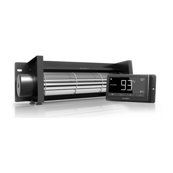
PRODUCT CONTENTS AIRBLAZE FIREPLACE BLOWER SYSTEM (Included in all series) BLOWER SENSOR POWER UNIVERSAL UNIT PROBE ADAPTER CONTROLLER (x1) (x1) (x1) (x1) WOOD MOUNTING VELCRO SCREW SCREWS STRIPS (x3) (x3) (x2) (x3) (x4) -
Page 8: Mounting
MOUNTING STEP 1 WARNING: Turn off the gas and electrical power before installing the kit! While the fireplace is cool and off, remove the lower half of the fireplace vent plate. Clean the inside of the area of any dust or dirt. STEP 2 While very carefully placing the blower towards the rear, be sure the opening of the fan in which... - Page 9 MOUNTING STEP 3 Be sure the metal plate is placed towards the wall of the vent and the rubber feet are placed against the floor with the fan blades facing forward as pictured in the illustration. STEP 4 Be sure that the area you are mounting has no gas lines or electrical wires in the way of the drilling area.
- Page 10 MOUNTING STEP 5 To mount the controller, position it on the outside of the vent away from the fireplace and use the included screw sets. Use a drill to screw the controller into place. STEP 6 Once the fan and Universal Controller are securely mounted with in a safe distance, you are now able to continue to powering.
-
Page 11: Powering
POWERING STEP 1 The blower unit comes corded with a 4-pin molex connector. Locate the connector and plug it into the bottom of the controller. Please make sure the this cord is secured away from contacting the blower’s spinning impeller and blades. STEP 2 Plug in the thermal probe directly under the controller, the probe has to be placed with in... - Page 12 POWERING STEP 3 To power the device, plug the adapter pin into the Universal controller, and the prong end into the outlet inside the fire place or outside the fireplace if there are no outlets. STEP 4 Follow the instructions starting on page 13 to program the controller.
-
Page 13: Programming
PROGRAMMING 1. MODE BUTTON 3. LEAF BUTTON 2. UP / DOWN BUTTON This button cycles through This turns the display off The up and down buttons each of the controller's while programs run in the adjusts the settings of the modes: ON, OFF, TIMER, background. - Page 14 PROGRAMMING MODE SETTING Press the Mode button to cycle through the controller’s available programming modes and settings: ON Mode, OFF Mode, TIMER Mode, AUTO Mode (4 triggers), ALARM Settings (4 settings). ON MODE In this mode, the fans will run continuously regardless of temperature or humidity.
- Page 15 PROGRAMMING AUTO MODE: HIGH TEMP. In this mode, press the up or down button to set a high temperature trigger. The fans will activate if the probe’s measured temperature exceeds the tem- perature you have set in this mode. The activated fans will slowly increase in speed until it reaches the speed set in ON Mode.
- Page 16 PROGRAMMING AUTO MODE: HIGH HUMID. In this mode, press the up or down button to set a high humidity trigger. The fans will activate if the probe’s measured humidity exceeds the humidity you have set in this mode. The activated fans will slowly increase in speed until it reaches the speed set in ON Mode.
- Page 17 PROGRAMMING ALARM SETTING: HIGH TEMP. In this settings mode, press the up and down button to set a high temperature alarm. The alarm will activate if the probe’s measured temperature exceeds the temperature you have set in this mode. When the alarm triggers, the fan will start spinning gradually to max speed regardless of your other settings.
- Page 18 PROGRAMMING ALARM SETTING: HIGH HUMID. In this settings mode, press the up and down button to set a high humidity alarm. The alarm will activate if the probe’s measured humidity exceeds the humidity you have set in this mode. When the alarm triggers, the fan will start spinning gradually to max speed regard- less of your other settings.
- Page 19 PROGRAMMING FAHRENHEIT OR CELSIUS To change to displayed units between Fahrenheit and Celsius, please set the controller to OFF Mode, then hold the up button for Fahrenheit (°F) or hold the down button for Celsius (°C). DISPLAY BRIGHTNESS To adjust the brightness of the display, please set the controller to OFF Mode, then press the up or down button to increase or decrease the brightness level.
- Page 20 PROGRAMMING ALERT ICONS On the top left of the display is the alert icon section. Icons may flash when the controller wishes to alert you that a particular function or alarm is being triggered. DISPLAY LOCK ALERT This icon is visible when the controller has been locked. The icon will flash to alert you that the controller is locked if you try to change the mode or settings.
-
Page 21: Other Ac Infinity Products
AC INFINITY PRODUCTS Register Booster Fans The AIRTAP series is a line of register booster fans designed to quietly increase airflow coming from your central heat and air conditioning systems, increasing comfort for your home. Features a thermal controller with intelligent programming that will automatically adjust airflow strength in response to heating and cooling temperatures you have set. -
Page 22: Warranty
This warranty program is our commitment to you, the original purchaser, that each product sold by AC Infinity will be free from defects in manufacturing for a period of two years from the date of purchase. If a product is found to have a defect in material or workmanship, we will take the appropriate actions defined in this warranty to resolve any issues. - Page 24 No part of the materials including graphics or logos available in this booklet may be copied, photocopied, reproduced, translated or reduced to any electronic medium or machine readable form, in whole or in part, without specific permission from AC Infinity Inc.
- Page 26 www.acinfinity.com...
Need help?
Do you have a question about the AIRBLAZE series and is the answer not in the manual?
Questions and answers