Table of Contents
Advertisement
Advertisement
Table of Contents

Related Manuals for AC Infinity Airlift Series


Summary of Contents for AC Infinity Airlift Series
- Page 1 AIRLIFT SERIES SHUTTER EXHAUST FAN SYSTEM USER MANUAL USER MANUAL...
- Page 3 WELCOME Thank you for choosing AC Infinity. We are committed to product quality and friendly customer service. If you have any questions or suggestions, please don’t hesitate to contact us. Visit www.acinfinity.com and click contact for our contact information. EMAIL LOCATION support@acinfinity.com...
- Page 4 MANUAL CODE AL1904X1 PRODUCT MODEL UPC-A AIRLIFT T10 AC-ALT10 819137020900 AIRLIFT T12 AC-ALT12 819137020917 AIRLIFT T14 AC-ALT14 819137020924 AIRLIFT T16 AC-ALT16 819137020948 AIRLIFT T18 AC-ALT18 819137020948 AIRLIFT T20 AC-ALT20 819137020955 AIRLIFT T22 AC-ALT22 819137020962 AIRLIFT T30 AC-ALT30 819137020986 AIRLIFT T36 AC-ALT36 819137020993 SERIOUS INJURY OR DEATH.
-
Page 5: Table Of Contents
MANUAL INDEX Manual Index ................. Page 5 Key Features ................. Page 6 Product Contents ................Page 7 Mounting ..................Page 8 Powering ..................Page 12 Programming ................. Page 13 Other AC Infinity Products ............. Page 21 Warranty ..................Page 22... -
Page 6: Key Features
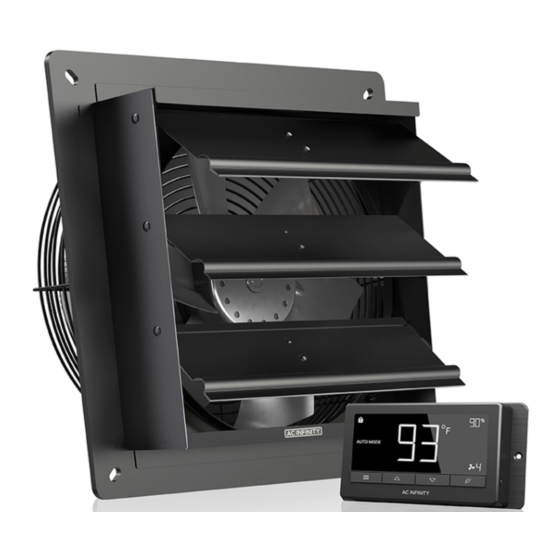
KEY FEATURES HEAVY DUTY BUILD WEATHERPROOF SMART CONTROLS Fans are enclosed in The shutter fan unit is sealed Programmable controller steel and wire guards to to Ingress Protection 44 with corded sensor can withstand shocks and harsh standards to be resistant to adjust airflow in response to environments. -
Page 7: Product Contents
PRODUCT CONTENTS AIRLIFT SHUTTER FAN SYSTEM (Included in all series) SHUTTER SENSOR UNIVERSAL FAN UNIT PROBE CONTROLLER (x1) (x1) (x1) WOOD MACHINE CONTROLLER WIRE SCREW SCREW SCREW SET TIES (x4) (x4) (x2) (x4) -
Page 8: Mounting
MOUNTING STEP 1 When installing in a large room like a green house, barn, or garage, it is recommended that the shutter fan should be mounted on the Mounting Hole opposite side of any ventilation openings for better air circulation. The fan should also be positioned higher in the room to exhaust out heated air, which will rise on its own due to natural convection. - Page 9 MOUNTING STEP 3 Depending on your mounting surface material, use the appropriate tools to cut into the wall. Use a drill or a hand saw to create an opening large enough to insert a saw blade or jigsaw inside the outlined area of the wall panel. Thinner Woods or Plastic Woods, Tougher Plastic or, Metal STEP 4...
- Page 10 MOUNTING STEP 5 From inside the room, position the shutter fan back into the opening of the fan. Make sure the controller connectors and power cord is on the inside of the room. Then, use the included hardware to secure the fan. Inside STEP 6 Once the fan is mounted securely you can...
- Page 11 POWERING STEP 1 Locate the connector plug of the thermal probe and plug it into the bottom of the thermal controller. STEP 2 Secure the thermal probe head near by, preferably in the hottest area of the room. You can use the wire tie to secure the probe away from the fan blades.
-
Page 12: Powering
POWERING STEP 3 Connect the molex end from the fan into the bottom of the controller. Be sure to plug it into the left molex 4 pin connector that has the power and fan icon, this plug is meant to power the controller. -
Page 13: Programming
PROGRAMMING 1. MODE BUTTON 3. LEAF BUTTON 2. UP / DOWN BUTTON This button cycles through This turns the display off The up and down buttons each of the controller's while programs run in the adjusts the settings of the modes: ON, OFF, TIMER, background. - Page 14 PROGRAMMING MODE SETTING Press the Mode button to cycle through the controller’s available programming modes and settings: ON Mode, OFF Mode, TIMER Mode, AUTO Mode (4 triggers), ALARM Settings (4 settings). ON MODE In this mode, the fans will run continuously re- gardless of temperature or humidity.
- Page 15 PROGRAMMING AUTO MODE: HIGH TEMP. In this mode, press the up or down button to set a high temperature trigger. The fans will activate if the probe’s measured temperature exceeds the tem- perature you have set in this mode. The activated fans will slowly increase in speed until it reaches the speed set in ON Mode.
- Page 16 PROGRAMMING AUTO MODE: HIGH HUMID. In this mode, press the up or down button to set a high humidity trigger. The fans will activate if the probe’s measured humidity exceeds the humidity you have set in this mode. The activated fans will slowly increase in speed until it reaches the speed set in ON Mode.
- Page 17 PROGRAMMING ALARM SETTING: HIGH TEMP. In this settings mode, press the up and down button to set a high temperature alarm. The alarm will activate if the probe’s measured temperature exceeds the temperature you have set in this mode. When the alarm triggers, the fan will start spinning at max speed regardless Note that alarm triggers can only of your other settings.
- Page 18 PROGRAMMING ALARM SETTING: HIGH HUMID. In this settings mode, press the up and down button to set a high humidity alarm. The alarm will activate if the probe’s measured humidity exceeds the humidity you have set in this mode. When the alarm triggers, the fan will start spinning at max speed regardless of your Note that alarm triggers can only other settings.
- Page 19 PROGRAMMING FAHRENHEIT OR CELSIUS To change to displayed units between Fahrenheit and Celsius, please set the controller to OFF Mode, then hold the up button for Fahrenheit (°F) or hold the down button for Celsius (°C). DISPLAY BRIGHTNESS To adjust the brightness of the display, please set the controller to OFF Mode, then press the up or down button to increase or decrease the brightness level.
- Page 20 PROGRAMMING ALERT ICONS On the top left of the display is the alert icon section. Icons may flash when the controller wishes to alert you that a particular function or alarm is being triggered. DISPLAY LOCK ALERT This icon is visible when the controller has been locked. The icon will flash to alert you that the controller is locked if you try to change the mode or settings.
- Page 21 AC INFINITY PRODUCTS Register Booster Fans The AIRTAP series is a line of register booster fans designed to quietly increase airflow coming from your central heat and air conditioning systems, increasing comfort for your home. Features a thermal controller with intelligent programming that will automatically adjust airflow strength in response to heating and cooling temperatures you have set.
-
Page 22: Warranty
WARRANTY This warranty program is our commitment to you, the product sold by AC Infinity will be free from defects in manufacturing for a period of two years from the date of purchase. If a product is found to have a defect in material or workmanship, we will take the appropriate actions defined in this warranty to resolve any issues. - Page 23 No part of the materials including graphics or logos available in this booklet may be copied, photocopied, reproduced, translated or reduced to any electronic medium or machine readable form, in whole or in part, without specific permission from AC Infinity Inc.
- Page 24 www.acinfinity.com...
Need help?
Do you have a question about the Airlift Series and is the answer not in the manual?
Questions and answers
i set the high temp triger point. then the high temp setting just blinks. is there something I need to do to activate the setting?