Advertisement
Quick Links
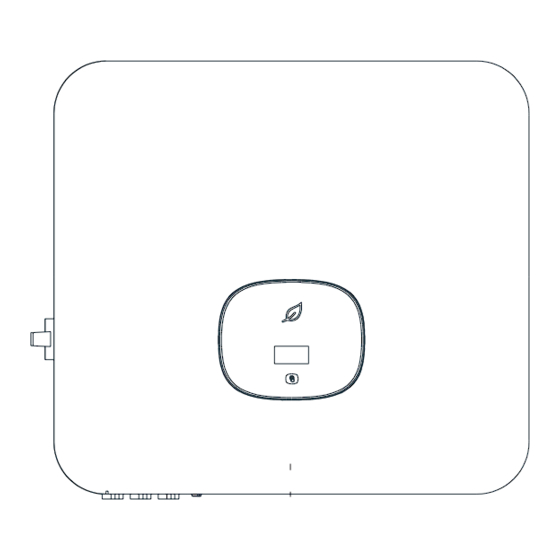
Overview
1
.
(3)LCD screen
(1)Front panel
(2)Touch button
(6)Heat sink
(7)DC switch
(8)PV terminal
(11)USB port
(12)Vent valve
(13)AC terminal
Note:
1.This document is for quick installation guidance only, please refer to User Manual for more details.
2.Growatt shall not be liable for any damage resulting from unproper installation.
2
Installation
.
System overview
2.1 Installation requirements
2.2
Wall mounting
Note:
1.When drilling holes in the wall, avoid water and electricity pipes, otherwise it may cause danger.
MOD 3-10KTL3-XH Quick Guide
(4)LED indicator
(5)Mounting bracket
(9)Battery terminal
(10)COM port
2.3
Communication module installation
Install
Inverter side
▲Up
Inverter side
3
Electrical connection
.
Please prepare the cable before connecting as follows.
No.
Cable name
Type
Single multi-core
Protective
1
yellow-green wire
grounding wire
Two or three polychromatic
2
AC output wire
multi-core copper wires
3
PV wire
PV input wire
4
RS485
3.1
3.2
Grounding
AC output connection
3.3
DC connection
3.3.1 PV/Battery input terminal installation
Positive metal terminal
8- 10mm
4mm - 6mm
²
²
4mm - 6mm
²
²
Negative metal terminal
Please make sure the cable can not be
pulled out after pressing.
Positive metal terminal
Negative metal terminal
Uninstall
Inverter side
Recommend model
Note:
6mm²-10mm²
1.Please make sure all switches are in "OFF"
position before wiring. For personal safety,
please do not operate with electricity.
6mm²-10mm²
2.If the diameter of the cable does not match
4mm²-6mm²
the terminal, or the cable is aluminum wire,
please contact our after-sales personnel.
4mm²-6mm²
/
Negative metal terminal
Pull the PV/BAT cable make sure there
is no loose or shaking.
Make sure the cable polarity is
correct and voltage is less than
1100V.
Inverter side
Advertisement

Related Manuals for Growatt 3-10KTL3-XH


Summary of Contents for Growatt 3-10KTL3-XH
- Page 1 1.Please make sure all switches are in “OFF” yellow-green wire grounding wire 2.Growatt shall not be liable for any damage resulting from unproper installation. position before wiring. For personal safety, Two or three polychromatic please do not operate with electricity.
- Page 2 L1/L2/L3/N-in Grid L1/L2/L3/N Service and contact L1/L2/L3/ 5/6/7/8 AC connector & Load L1/L2/L3/N Shenzhen Growatt New Energy Co., Ltd N-out 4-13/F,Building A,Sino-German(Europe) Industrial Park, Hangcheng Ave, Bao’an District, Shenzhen, China RS485A COM Port Pin 5 RS485A3 +86 0755 2747 1942...
Need help?
Do you have a question about the 3-10KTL3-XH and is the answer not in the manual?
Questions and answers