Table of Contents
Advertisement
Quick Links
Advertisement
Table of Contents

Related Manuals for Ublox EVK-JODY-W3


Summary of Contents for Ublox EVK-JODY-W3
- Page 1 EVK-JODY-W3 Evaluation kit for JODY-W3 host-based modules User guide Abstract This document describes how to set up the EVK-JODY-W3 evaluation kit to evaluate JODY-W3 series multiradio modules with Wi-Fi and Bluetooth. UBX-20030840 - R02 C1 – Public www.u-blox.com...
-
Page 2: Document Information
EVK-JODY-W3 - User guide Document information Title EVK-JODY-W3 Subtitle Evaluation kit for JODY-W3 host-based modules Document type User guide Document number UBX-20030840 Revision and date 2-Nov-2020 Disclosure restriction C1 – Public This document applies to the following products: Product name... -
Page 3: Table Of Contents
EVK-JODY-W3 - User guide Contents Document information ..........................2 Contents ............................... 3 Kit description ............................4 1.1 Overview ................................ 4 1.2 Kit includes ..............................6 1.3 Software ................................ 7 1.4 System requirements ..........................7 Specifications ............................8 2.1 Operating conditions ..........................8 Getting started ............................ -
Page 4: Kit Description
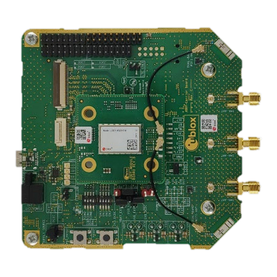
PCIe or SDIO for Wi-Fi, SDIO or high-speed UART for Bluetooth, and PCM/I2S for Bluetooth audio. EVK-JODY-W3 allows an external host processor to access several practical features for testing and evaluating the Wi-Fi and Bluetooth connectivity supported in JODY-W3 series modules, including: •... - Page 5 Figure 1: EVK-JODY-W3 outline showing main connectors The EVK-JODY-W3 design is split into a module board and a carrier board. The module board includes the JODY-W3 series module and u.FL antenna connectors directly accessing the antenna pins on the module.
-
Page 6: Kit Includes
EVK-JODY-W3 - User guide 1.2 Kit includes Table 2 shows the various components included in the EVK-JODY-W3. Part Description Outline Evaluation board (EVB) Evaluation board for the JODY-W3 series modules. The board includes SMA antenna connectors that connect to external antennas for Wi-Fi and Bluetooth. -
Page 7: Software
EVK-JODY-W3 - User guide 1.3 Software The software package including the reference driver from NXP is only distributed to customers that have signed a Limited Use License Agreement (LULA-M) with u-blox. For information about how to obtain the driver package, contact your local u-blox support team. The software package and additional documentation can also be obtained directly from NXP. -
Page 8: Specifications
EVK-JODY-W3 - User guide Specifications This section includes the different operating parameters for the EVK-JODY-W3. 2.1 Operating conditions Table 3 describes the absolute range for key EVK operating parameters. Symbol Parameter Min. Max. Units Power supply voltage 3.14 3.46 I/O supply voltage 1.8 V 1.71... -
Page 9: Getting Started
Figure 1 shows an overview of the EVK and its main connectors. For more detailed description of the available connectors and configuration options, see section 4 . Follow the procedure below to evaluate JODY-W3 series module using EVK-JODY-W3: Connect the internal or external antennas to the EVK: EVK-JODY-W374 uses the two internal dual-band antennas by default for any Wi-Fi and Bluetooth communication. - Page 10 EVK-JODY-W3 - User guide module. Figure 2: PCIe and USB connectors For SDIO connection, connect the micro SDIO adapter card with the flat cable to the SDIO connector (J204) on the EVK as shown in Figure 3 and insert the adapter card into an SDIO connector of the host system.
- Page 11 EVK-JODY-W3 - User guide Bluetooth, communication with the JODY-W3 series module. Figure 3: SDIO connector A high speed UART interface can be used for Bluetooth communication with the JODY-W3 series module. A USB-to-UART bridge is included on the evaluation board. To use the Bluetooth interface through USB, connect the included USB cable to the USB type-C connector on the EVK (see Figure 2) and connect it to a USB interface on the host system.
-
Page 12: Board Description
GPIOs (PCM/I2S) codec Figure 4: EVK-JODY-W3 block diagram 4.2 Overview of jumpers and connectors Figure 5 shows an overview of the evaluation board and its connectors. The EVK makes all the interfaces of the JODY-W3 series module accessible through connectors or pin headers. The available interfaces and configurations options are described in detail in the following sections. - Page 13 JODY-W3 module board SW500, SW501: Reset and power J301: buttons Bluetooth audio LEDs interface J406, J408, J410: SMA Internal dual-band connectors for external antennas antennas Figure 5: EVK-JODY-W3 jumpers and connectors UBX-20030840 - R02 Board description Page 13 of 29...
-
Page 14: Jumper Conventions
DC-DC converters on the EVK. • External power supply (VEXT): EVK-JODY-W3 can be connected to an external power supply of 7 V to 24 V. DC-DC converters are used for generating all the required internal voltages. •... - Page 15 EVK-JODY-W3 - User guide Figure 7 describes the external power supply connectors and jumpers to configure the different power supply options. LEDs for external power supply selection Single external power supply connector Jumpers for input voltage muxing for the module...
-
Page 16: Power Supply Selection
EVK-JODY-W3 - User guide Figure 9: Power supply and input voltage selection 4.3.1 Power supply selection The selection for the external power supply sources is shown in Figure 10. Figure 10: External power supply sources 3V3_IN is the input to the DC-DC converters on the EVK to generate the 3.3 V and 1.8 V voltages. The jumpers J104-J106 are used to select to external power supply input for the EVK. -
Page 17: Input Voltage Selection
Table 6: Input voltage options For the operation of EVK-JODY-W3, power supply jumpers must be set as explained in Table 5 and Table 7. The first one selects the external power supply and the second one defines the voltage levels to operate the module. -
Page 18: Pcie Interface
EVK-JODY-W3 - User guide Power supply using individual external input sources for each of the voltage rails 3V3, 1V8 and VIO. External supplies are connected at the bottom of the EVK carrier board. Note: VIO can also be connected to VBAT or 1V8 to supply it from the same external 3.3 V or 1.8 V source. -
Page 19: Bluetooth Uart Interface
EVK-JODY-W3 - User guide Figure 13: SDIO interface connector All signals except VDD_SDIO are directly connected to the JODY-W3 module through 22 Ω series resistors connected on the module board. VDD_SDIO is connected to the power supply connector (J105) and is used for supplying 3.3 V for VBAT from the SDIO interface. -
Page 20: Bluetooth Audio Interface
EVK-JODY-W3 - User guide Name Description Remarks UART_TXD UART TX signal Connect to Host RX UART_RXD UART RX signal Connect to Host TX UART_RTS UART RTS signal Connect to Host CTS UART_CTS UART CTS signal Connect to Host RTS Table 8: UART signal description 4.7 Bluetooth audio interface... -
Page 21: Other Interfaces
EVK-JODY-W3 - User guide 4.8 Other interfaces Connectors J301 (Figure 18) and J303 (Figure 17) provide several other interfaces from the JODY-W3 series module, such as host wake-up signals, GPIOs, and audio interfaces. Figure 17: Connector J303 Figure 18: Connector J301 4.9 Bootstrapping... -
Page 22: Antenna Interfaces
EVK-JODY-W3 - User guide SW503 CON_2 CON_1 CON_0 M_RST OFF=1 ON=0 Figure 19: Boot and host interface configuration Table 10 describes the DIP switch positions for configuring the boot mode and host interface options. Boot mode CON_2 CON_1 CON_0 Description... - Page 23 EVK-JODY-W3 - User guide Default antenna configurations for EVK-JODY-W374 and EVK-JODY-W377 are shown in Figure 20 and Figure 21, respectively. ANT2 ANT0 ANT1 ANT401 ANT400 SMA2 SMA0 SMA1 Figure 20: Default antenna configuration for EVK-JODY-W374 ANT2 ANT0 ANT1 ANT400 ANT401...
-
Page 24: Leds
EVK-JODY-W3 - User guide 4.11 LEDs Table 12 describes the function and designation of the available LEDs on the EVK-JODY-W3 evaluation board. Function Description Designator Color VDD_EXT External voltage supplied D401 Green VBAT Main power supply (VBAT) status indication D402 Green VIO Supply (1.8 V or 3.3 V) -
Page 25: Appendix
USB cable only after PCI initialization. • When using the EVK-JODY-W3 with NXP i.MX8 series platforms, the SDIO interface cannot be used to draw the power for the module. To work around this issue, draw power through USB or external power supplies. -
Page 26: B Glossary
EVK-JODY-W3 - User guide B Glossary Abbreviation Definition Evaluation board Evaluation kit Host controller interface Input / output Inter-Integrated circuit sound Light-Emitting Diode Low-dropout regulator Low-power oscillator Long-Term Evolution Medium access control MIMO Multiple input multiple output Multimedia card Personal computer... -
Page 27: Related Documents
EVK-JODY-W3 - User guide Related documents JODY-W3 series data sheet, UBX-19010615 JODY-W3 system integration manual, UBX-19011209 JODY-W2 level shifter integration application note, UBX-19034257 EVK-JODY-W3 schematics ☞ For product change notifications and regular updates of u-blox documentation, register on our website, www.u-blox.com. -
Page 28: Revision History
EVK-JODY-W3 - User guide Revision history Revision Date Name Comments 9-Jul-2020 mzes Initial release. 2-Nov-2020 mzes Minor editorial updates. Released for public distribution. UBX-20030840 - R02 Revision history Page 28 of 29 C1 – Public... -
Page 29: Contact
EVK-JODY-W3 - User guide Contact For complete contact information, visit us at www.u-blox.com. u-blox Offices North, Central and South America Headquarters Asia, Australia, Pacific Europe, Middle East, Africa u-blox America, Inc. u-blox Singapore Pte. Ltd. u-blox AG Phone: +1 703 483 3180...
Need help?
Do you have a question about the EVK-JODY-W3 and is the answer not in the manual?
Questions and answers