Table of Contents
Advertisement
Quick Links
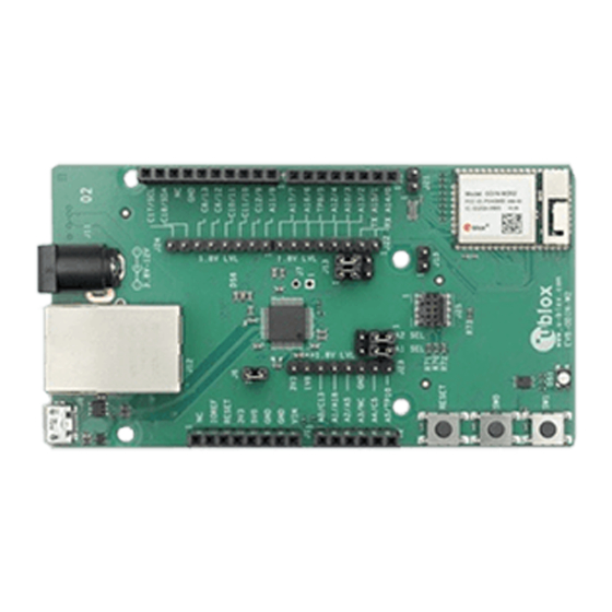
EVK-ODIN-W2
Evaluation Kit for ODIN-W2
User guide
Abstract
This document describes how to set up the EVK-ODIN-W2 evaluation kit and provides information
for evaluating and testing the u-blox ODIN-W2 multiradio standalone module with u-connectXpress
software or for embedded custom applications using the Arm
www.u-blox.com
UBX-16007132 - R07
®
Mbed™ development tool.
Advertisement
Table of Contents

Related Manuals for Ublox EVK-ODIN-W2


Summary of Contents for Ublox EVK-ODIN-W2
- Page 1 Evaluation Kit for ODIN-W2 User guide Abstract This document describes how to set up the EVK-ODIN-W2 evaluation kit and provides information for evaluating and testing the u-blox ODIN-W2 multiradio standalone module with u-connectXpress software or for embedded custom applications using the Arm ®...
-
Page 2: Document Information
EVK-ODIN-W2 - User guide Document information Title EVK-ODIN-W2 Subtitle Evaluation Kit for ODIN-W2 Document type User guide Document number UBX-16007132 Revision and date 6-Sep-2019 Disclosure restriction This document applies to the following products: Product name Type number Software version PCN reference... -
Page 3: Table Of Contents
EVK-ODIN-W2 - User guide Contents Document information ..........................2 Contents ................................3 Product description ..........................4 1.1 Overview ................................ 4 1.2 Kit includes ..............................5 1.3 Jumper description ............................ 5 1.4 LEDs ................................5 1.5 Connectors ..............................6 1.6 ODIN-W2 pin assignment .......................... 7 1.7 Buttons ................................ -
Page 4: Product Description
The wireless support includes dual-mode Bluetooth v4.0 (BR/EDR and low energy) and dual-band Wi-Fi (2.4 and 5 GHz bands). This document describes how to set up the EVK-ODIN-W2 evaluation kit and provides information for evaluating and testing the u-blox ODIN-W2 multiradio standalone module with u-connectXpress software or using the Arm ®... -
Page 5: Kit Includes
Selects whether the 32.768 kHz LPO oscillator is connected to Not mounted oscillator ODIN-W2 or not ODIN-W2 Boot Selects whether to force ODIN-W2 into Boot mode or not Not mounted Table 1: EVK-ODIN-W2 jumper description 1.4 LEDs Function Description Name Color RGB/SPA status RGB LED shows status for u-connectXpress. -
Page 6: Connectors
USB connector Table 3: EVK-ODIN-W2 connector description On the EVK-ODIN-W2 evaluation board, there are two sets of connectors for accessing the ODIN-W2 pins. The socket connectors (J2, J3, and J4) placed closely to the board edges are connected to ODIN- W2 through level shifters and have 3.3 V I/O level. -
Page 7: Odin-W2 Pin Assignment
Refer to ODIN-W2 series System Integration Manual [1] for information about pin assignment. Buttons The EVK-ODIN-W2 evaluation board has three buttons. All these buttons are directly connected to pins on the ODIN-W2 module. The SW0 and SW1 buttons are grounded only when pressed; otherwise they float. -
Page 8: Configurations Options
EVK-ODIN-W2 - User guide 1.9 Configurations options 1.9.1 UART selection for virtual COM port It is possible to select either UART1 or UART3 to be relayed through the onboard debugger as a virtual COM port available at the USB connector. -
Page 9: Odin-W2 Boot
1.9.4 SWD Cortex debug connector The EVK-ODIN-W2 has an onboard ST-Link v2.1 debugger. You can also connect an external debugger to the ODIN-W2 module via the 10-pin SWD Cortex debug connector J25. The onboard debugger should be enabled (jumper on position J6 mounted) even if using an external debugger. -
Page 10: Khz Lpo Oscillator
32.768 kHz LPO oscillator There is an onboard 32.768 kHz oscillator on the EVK-ODIN-W2. The output signal of this oscillator can be connected to ODIN-W2 by putting a jumper on pin header J21. The LPO is used for the Wi-Fi chip to enable entering low power modes. -
Page 11: Getting Started
You should install the ST-link utility and drivers before connecting the USB cable to your PC. ⚠ There can be some issues while using the EVK-ODIN-W2 with Windows 10. To avoid these issues, upgrade the ST-link firmware on the debug chip and make sure that you have the latest USB mass storage device driver. -
Page 12: Usage With Uart Flow Control
Usage with UART flow control To set up the EVK-ODIN-W2 evaluation board for use with the u-blox connectivity software and flow control, see Table 4 for pin description. If you require the USB interface, a Serial to USB FTDI cable can be used on the headers in the 1.8 V I/O domain. -
Page 13: Mbed Os 3
EVK-ODIN-W2 - User guide In addition to creating a GitHub user account, it is recommended to install a Git command-line tool to manage the Git repositories. Go to https://git-scm.com/downloads and follow the installation instructions. ☞ Ensure “Use Git from the Windows Command Prompt” is selected in the “Adjusting your PATH environment”... -
Page 14: Appendix
EVK-ODIN-W2 - User guide Appendix Updating the ST-link software Due to an incompatibility between the ST-link software in the debug chip and Windows 10, the EVKs produced before December 01, 2016 will not work with Windows 10. Connecting them to a PC running Windows 10 will corrupt the bootloader of ODIN-W2 and the EVK will stop working. -
Page 15: Schematic
EVK-ODIN-W2 - User guide Schematic Figure 10: Placement on EVK-ODIN-W2 UBX-16007132 - R07 Appendix Page 15 of 22... - Page 16 EVK-ODIN-W2 - User guide UBX-16007132 - R07 Appendix Page 16 of 22...
- Page 17 EVK-ODIN-W2 - User guide UBX-16007132 - R07 Appendix Page 17 of 22...
- Page 18 EVK-ODIN-W2 - User guide UBX-16007132 - R07 Appendix Page 18 of 22...
- Page 19 EVK-ODIN-W2 - User guide UBX-16007132 - R07 Appendix Page 19 of 22...
-
Page 20: Glossary
EVK-ODIN-W2 - User guide Glossary Name Definition Communication Clear to send Enhanced data rate Evaluation kit Ground GPIO General-Purpose Input/Output Light-Emitting Diode Low power oscillator Multipoint control unit MIMO Multiple input multiple output PIFA Planar Inverted-F Antenna Physical layer (of the OSI model) -
Page 21: Related Documents
EVK-ODIN-W2 - User guide Related documents ODIN-W2 series System integration manual, Doc. No. UBX-14040040 ODIN-W2 series in Arm® Mbed™ environment system integration manual – Mbed addendum, Doc. No. UBX-16008405 ODIN-W2 Online resources https://www.u-blox.com/en/product/odin-w2-series ODIN-W2 series data sheet, Doc. No. UBX-14039949 u-connectXpress software user guide, Doc. -
Page 22: Contact
EVK-ODIN-W2 - User guide Contact For complete contact information, visit us at www.u-blox.com. u-blox Offices North, Central and South America Headquarters Asia, Australia, Pacific Europe, Middle East, Africa u-blox America, Inc. u-blox Singapore Pte. Ltd. u-blox AG Phone: +1 703 483 3180...
Need help?
Do you have a question about the EVK-ODIN-W2 and is the answer not in the manual?
Questions and answers