Ublox TOBY-L2 Series User Manual
Lte/dc-hspa+/egprs cellular evaluation kits
Hide thumbs
Also See for TOBY-L2 Series:
- System integration manual (141 pages) ,
- System integration manual (164 pages) ,
- System integration manual (158 pages)
Table of Contents
Advertisement
Quick Links
Advertisement
Table of Contents

Subscribe to Our Youtube Channel
Related Manuals for Ublox TOBY-L2 Series


Summary of Contents for Ublox TOBY-L2 Series
- Page 1 EVK-L2 TOBY-L2 series LTE/DC-HSPA+/EGPRS Cellular Evaluation Kits User Guide Abstract This guide explains how to set up the EVK-L2x Evaluation Kits to begin evaluating the u-blox TOBY-L2 series LTE/DC-HSPA+/EGPRS cellular modules. www.u-blox.com UBX-14000422 - R10...
- Page 2 EVK-L2 - User Guide Document Information Title EVK-L2 TOBY-L2 series Subtitle LTE/DC-HSPA+/EGPRS Cellular Evaluation Kits Document type User Guide Document number UBX-14000422 Revision, date 26-Jun-2017 Disclosure restriction This document applies to the following products: Name Type number Modem version Application version...
-
Page 3: Table Of Contents
EVK-L2 pin out ........................... 10 1.6.1 EVK-L2 for TOBY-L2 series modules, product version "01" ............10 1.6.2 EVK-L2 for TOBY-L2 series modules, product versions "02" / "62" onwards ....... 12 Software installation ........................... 13 Board setup ............................14 Enabling error result codes ......................... 15 1.10... -
Page 4: Starting Up
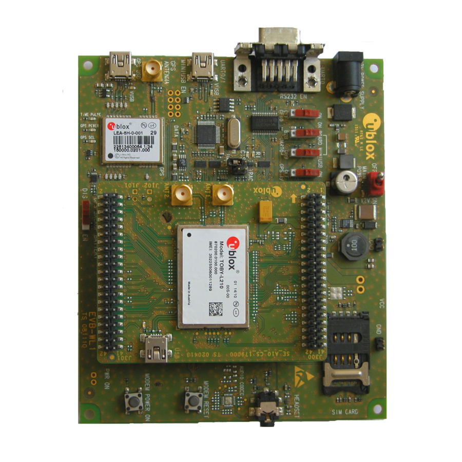
This document identifies all the EVK-L20, EVK-L21, EVK-L22, EVK-L23 and EVK-L24 evaluation kits as EVK-L2. This section describes the main connections and settings required to get started. See the TOBY-L2 series Data Sheet [3] and TOBY-L2 / MPCI-L2 series System Integration Manual [4] for the features supported by u-blox TOBY-L2 series LTE/DC-HSPA+/EGPRS cellular modules. - Page 5 EVK-L2 - User Guide Cellular RS232 Cellular USB 9 – 18 V GNSS USB (UART) (UART) Power input J102 J500 J501 J400 DS124 DS118 DL405 DL403 DL501 SW300 GNSS DL404 adapter board Main power switch SW400 GNSS antenna connector DL401 J103 GNSS module DS132...
- Page 6 EVK-L2 - User Guide Cellular RS232 Cellular USB 9 – 18 V GNSS USB (UART) (UART) Power input J102 J500 J501 J400 DS124 DS118 DL405 DL403 DL501 SW300 GNSS DL404 adapter board Main power switch SW400 GNSS antenna connector DL401 J103 GNSS module DS132...
-
Page 7: Evk-L2 Block Diagram
Figure 3: Block diagram of EVK-L2 for TOBY-L2 product versions "01" (top) and "02" / "62" onwards (bottom) The EVK-L2 is formed by three boards: The lower one, called EVB-WL3, contains the power supply and other peripherals for the TOBY-L2 series cellular module (SIM card holder, Reset button and Power-on button). ... -
Page 8: Switches, Jumpers And Buttons
EVK-L2 - User Guide 1.3 Switches, jumpers and buttons Function Description Name Board Main Power Switch Power on / off of the whole evaluation kit SW400 Cellular VCC Jumper socket to provide the 3.8 V supply to the cellular module VCC input J404 Cellular Power-on Push button to switch-on the cellular module... -
Page 9: Connectors
EVK-L2 - User Guide 1.5 Connectors Function Description Name Board 9 - 18 V Power Input Connector for the AC / DC power adapter of the EVK IEC 60417-5172 J400 AC: 100-240 V, 0.8 A, 50-60 Hz / DC: +12 V, 2.5 A Class II equipment SIM card holder SIM card holder... -
Page 10: Evk-L2 Pin Out
J301 Pin 4 93-152 J301 Pins 7-10 Table 4: Interfaces of TOBY-L2 series module, product version "01", as routed on the 42-pin Dual-In-Line Board-to-Board connectors (J300, J301) available on the adapter board ADP-L2 of the EVK-L2 evaluation kit UBX-14000422 - R10... - Page 11 The pins / interfaces that are not supported by a specific TOBY-L2 module product version should not be driven by an external device (see the TOBY-L2 series Data Sheet [3] and TOBY-L2 / MPCI-L2 series System Integration Manual [4] for the features supported by each TOBY-L2 module product version).
-
Page 12: Evk-L2 For Toby-L2 Series Modules, Product Versions "02" / "62" Onwards
93-152 J201 Pins 7-10 Table 6: Interfaces of TOBY-L2 series modules, product version "02" / "62" onward, as routed on the 42-pin Dual-In-Line Board- to-Board connectors (J200, J201) available on the adapter board ADP-L2 of the EVK-L2 evaluation kit 0R jumper can be populated in order to route the signal to the 42-pin Dual-In-Line Board-to-Board connectors... -
Page 13: Software Installation
The pins / interfaces that are not supported by a specific TOBY-L2 module product version should be not driven by an external device (see the TOBY-L2 series Data Sheet [3] and TOBY-L2 / MPCI-L2 series System Integration Manual [4] for the features supported by each TOBY-L2 module product version). -
Page 14: Board Setup
EVK-L2 - User Guide 1.8 Board setup Insert a SIM card into the SIM card holder (J300 on the EVB). Connect a cellular antenna provided with the evaluation kit box to the Primary cellular antenna SMA connector on the ADP-L2 (ANT1, RF input/output for transmission and reception of LTE/3G/2G RF signals). Connect a cellular antenna provided with the evaluation kit box to the Secondary cellular antenna SMA connector on the ADP-L2 (ANT2, RF input for the reception of the LTE RF signals as per the Down-Link MIMO 2 x 2 and for the reception of the 3G RF signals as per the Down-Link Rx diversity). -
Page 15: Enabling Error Result Codes
EVK-L2 - User Guide 10. For communication via the TOBY-L2 module’s UART interface, the following connections are allowed and can be alternatively enabled in a mutually exclusive way (see Table 8 for switch position and LED status): Connect a USB cable to mini USB connector (Cellular USB, J501 on EVB), LED DL501 lights blue Connect an RS232 cable to DB9 connector (Cellular RS232, J500 on EVB) When a USB cable is connected to the mini USB connector, two COM ports are enabled in Windows (the numbering of the COM ports can be seen via the Windows Device Manager). -
Page 16: Registration On A Cellular Network
EVK-L2 - User Guide 1.11 Registration on a cellular network Command sent by DTE (user) DCE response (module) Description AT+CREG? +CREG: 0,1 Verify the network registration. AT+COPS=0 Register the module on the network. The cellular module automatically registers itself on the cellular network. -
Page 17: Appendix
EVK-L2 - User Guide Appendix A Setting up AT terminal applications for communication with EVK-L2 The u-blox m-center cellular module evaluation tool is a powerful platform for evaluating, configuring and testing u-blox cellular products. m-center includes an AT commands terminal for communication with the device and can be downloaded free-of-charge from our website (http://www.u-blox.com). -
Page 18: Bevk-L2 Setup For Internet Browsing (Windows)
This section describes how to set up the EVK-L2 for browsing the internet with Windows 7 operating system on a PC connected with the EVK-L2 over the USB physical interface of the TOBY-L2 series module. Follow the board setup instructions described in section 1.8 in order to provide communication via the USB interface of the TOBY-L2 series module. - Page 19 EVK-L2 - User Guide Open “Network and Sharing Center” and click on Local Area Connection (associated to RNDIS interface): Click on Properties: UBX-14000422 - R10 Appendix Page 19 of 30...
- Page 20 EVK-L2 - User Guide Search for “Internet Protocol Version 4 (TCP/IPv4)” and click on Properties: Check the Obtain an IP address automatically and Obtain DNS server address automatically option. This the DHCP UBX-14000422 - R10 Appendix Page 20 of 30...
- Page 21 EVK-L2 - User Guide If it is not possible to surf the web, then manually set the DNS server address: for example, use the DNS server returned by network (in this example, 83.224.70.94) UBX-14000422 - R10 Appendix Page 21 of 30...
-
Page 22: Cevk-L2 Setup For Internet Browsing (Linux)
This section describes how to set up the EVK-L2 for browsing the internet with a Linux operating system on a PC connected with the EVK-L2 over the USB interface of the TOBY-L2 series module. Follow the board setup instructions described in section 1.8 (except the Windows OS settings) to provide communication via the USB interface of the TOBY-L2 module. - Page 23 For the complete description and syntax of supported AT commands, and for further details regarding all the settings configurable by means of AT commands, see the u-blox AT Commands Manual [1], the u-blox AT Commands Examples Application Note [2], and the u-blox TOBY-L2 series Networking Modes Application Note [5].
- Page 24 EVK-L2 - User Guide Use the command dhclient usb0 to configure the DHCP client, now the RNDIS is active. Use ifconfig to check that RNDIS is now active. Now it is possible to browse the Internet. UBX-14000422 - R10 Appendix Page 24 of 30...
-
Page 25: D Optimal Throughput
EVK-L2 - User Guide D Optimal throughput To reach the highest throughput use one of these interfaces, which are listed with most optimal first: the RNDIS interface the CDC-ECM interface the CDC-ACM interface The configuration can be set by means of the +UUSBCONF AT command (see the u-blox AT Commands Manual [1]). -
Page 26: E Examples Of At Commands
EVK-L2 - User Guide E Examples of AT commands For the complete description and syntax of the AT commands supported by each TOBY-L2 series cellular module product version, see the u-blox AT commands Manual [1]. For detailed examples of AT commands for network registration and configuration, context activation, data connection management, SIM management, module interfaces configurations and other settings, see the u-blox AT Commands Examples Application Note [2]. -
Page 27: F Current Consumption Measurement
F.1 EVK-L2 for TOBY-L2 modules, product version "01" Current consumption of TOBY-L2 series modules, product version "01" can be measured on the EVK-L2 by removing the jumper socket from the Cellular VCC supply jumper (J404 on the EVB), described in Figure 6. -
Page 28: Evk-L2 For Toby-L2 Modules, Product Versions "02"/ "62" Onwards
F.2 EVK-L2 for TOBY-L2 modules, product versions "02"/ "62" onwards Current consumption of TOBY-L2 series module product versions "02" / "62" onwards can be measured on the EVK-L2 by removing 0R jumpers R118 and R115 mounted on the cellular adapter board, described in Figure 8. -
Page 29: Declaration Of Conformities
TOBY-L2 series Data Sheet, Docu No UBX-13004573 u-blox TOBY-L2 / MPCI-L2 series System Integration Manual, Docu No UBX-13004618 u-blox TOBY-L2 series Networking Modes Application Note, Docu No UBX-14000479 u-blox Wi-Fi / Cellular Integration Application Note, Docu No UBX-14003264 All these documents are available on our website (http://www.u-blox.com). -
Page 30: Contact
EVK-L2 - User Guide Contact For complete contact information visit us at www.u-blox.com u-blox Offices North, Central and South America Headquarters Asia, Australia, Pacific Europe, Middle East, Africa u-blox America, Inc. u-blox Singapore Pte. Ltd. u-blox AG Phone: +1 703 483 3180 Phone: +65 6734 3811 E-mail:... - Page 31 Mouser Electronics Authorized Distributor Click to View Pricing, Inventory, Delivery & Lifecycle Information: u-blox EVK-L20 EVK-L21 EVK-L22 EVK-L23 EVK-L24...
Need help?
Do you have a question about the TOBY-L2 Series and is the answer not in the manual?
Questions and answers