Table of Contents
Advertisement
Quick Links
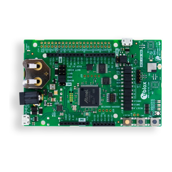
EVK-ANNA-B4
Evaluation kit for ANNA-B4 modules
User guide
Abstract
This document describes how to set up the EVK-ANNA-B4 evaluation kit to evaluate ANNA-B4
series standalone Bluetooth
debugging and testing the development capabilities supported by the evaluation board.
UBX-21008123 - R02
C1-Public
®
5.1 low energy modules. It also describes the different options for
www.u-blox.com
Advertisement
Table of Contents

Subscribe to Our Youtube Channel
Related Manuals for Ublox EVK-ANNA-B4


Summary of Contents for Ublox EVK-ANNA-B4
- Page 1 EVK-ANNA-B4 Evaluation kit for ANNA-B4 modules User guide Abstract This document describes how to set up the EVK-ANNA-B4 evaluation kit to evaluate ANNA-B4 series standalone Bluetooth ® 5.1 low energy modules. It also describes the different options for debugging and testing the development capabilities supported by the evaluation board.
-
Page 2: Document Information
Document information Title EVK-ANNA-B4 Subtitle Evaluation kit for ANNA-B4 modules Document type User guide Document number UBX-21008123 Revision and date 19-Oct-2021 Disclosure restriction C1-Public This document applies to the following products: Product name Type number Firmware version PCN reference EVK-ANNA-B402U... -
Page 3: Table Of Contents
Product description ..........................6 2.1 Overview ................................ 6 2.2 Kit includes ..............................7 2.3 Key features ..............................7 2.4 EVK-ANNA-B4 block diagram ........................9 2.5 Connectors ..............................10 Setting up the evaluation board ....................11 3.1 Software and hardware preparation ..................... 11 Installing software .......................... - Page 4 EEPROM support ..........................31 5.4 Additional Interfaces ..........................31 Extra USB to UART interface ......................33 CPU trace interface .......................... 33 Appendix ..............................34 Schematics ............................34 Assembly drawings ......................... 38 Glossary .............................. 40 Related documents ..........................41 Revision history ............................41 Contact ...............................
-
Page 5: Quick Start Guide
Follow the procedure outlined below to install the J-Link drivers needed for programming the module. 1. Connect the EVK-ANNA-B4 board to your PC using the USB cable provided with the product. 2. Verify that the USB drivers are installed successfully. If the drivers do not install automatically,... -
Page 6: Product Description
Product description 2.1 Overview The EVK-ANNA-B4 evaluation kit is a versatile development platform that allows quick prototyping of a variety of extremely low-powered Internet of Things (IoT) applications, using full Bluetooth 5.1, NFC, and IEEE 802.15.4. EVK-ANNA-B4 boards are available in the following four variants that accommodate alternative antenna and software solutions: •... -
Page 7: Kit Includes
-M4F microcontroller with a 64 MHz system clock, 512 kB internal flash and 128 kB RAM. EVK-ANNA-B4 evaluation boards provide access to the 33 GPIO pins and interfaces supported on ANNA-B4 modules. The interfaces are available through a variety of connectors, including Arduino™... - Page 8 • ANNA-B412 with u-connectXpress software, based on Nordic nRF52833 SoC, Bluetooth 5.1 Low Energy modules: Ultra-compact SiP (6.5 x 6.5) offering both internal and external antenna options Pre-flashed u-connectXpress software for accelerated time to market Integrated Arm® Cortex®-M4F microcontroller with 64 MHz system clock Pre-flashed u-connectXpress software supporting u-blox Bluetooth Low Energy Serial Port Service, GATT client and server, beacons, Bluetooth long range, NFC™, and simultaneous peripheral and central roles.
-
Page 9: Evk-Anna-B4 Block Diagram
2.4 EVK-ANNA-B4 block diagram Figure 2 shows the major interfaces and internal connections supported on the EVK-ANNA-B4. ANNA Connectivity Software function UART UART GPIO/Dig. Int. ANNA Open CPU function GPIO/Dig. Interface GPIO/Dig. Interface ADC/Comp. Arduino pin Arduino Uno R3 interface... -
Page 10: Connectors
2.5 Connectors Table 1 describes the available connectors of the EVK-ANNA-B4 shown in Figure 3. Connector Function Description Power supply 2.1 mm power jack. The center pin of the connector is the positive terminal. 5 – 12 V input. Power supply Pin header for connecting external power supplies. -
Page 11: Setting Up The Evaluation Board
External antennas are therefore not needed for evaluating these board variants 3.1.2.2 NFC antenna To use any of the EVK-ANNA-B4 board variants as an NFC tag, an NFC antenna can be connected to the NFC antenna connector (J11) . Power on evaluation board... -
Page 12: Assigning Com Ports
Plug the external power supply to the power jack connector (J5), or connect a USB host to the USB connector (J8) with a USB cable. Alternatively, you can power on a EVK-ANNA-B4 evaluation board with a CR2032 coin cell battery. See also Powering options for more details. -
Page 13: Measuring Current Consumption
3.2.2.2 Software debug options Use either of the following options to debug software with EVK-ANNA-B402: • Onboard debug solution available through the USB connector • External debugger connected to J12 connector An external debugger is useful when powering the evaluation board with a CR2032 coin cell battery or an external power supply through the power jack connector J5. -
Page 14: Using An External Power Supply Or Power Analyzer
Using an external power supply or power analyzer To measure the power consumption of the ANNA modules, connect the instrument terminals to the J22 pins, as shown in Figure 4. Since the external voltage of any connected instrument can never perfectly match the 3.3 V generated by the EVK, some small current leakage is apparent whenever the signal from the ANNA module is connected to an EVK peripheral. -
Page 15: Board Configuration
Figure 5: Block diagram of the power net distribution Selecting the power configuration jumpers EVK-ANNA-B4 offers flexible powering options for the ANNA-B4 module and the board itself. To configure the power options, jumpers are added to or removed from pin headers to connect or disconnect different power nets on the evaluation board. - Page 16 Sources Net names Targets DC/DC VDD_MCU Onboard 3.3 V PC communication converter 3V3_PI VBAT Raspberry Pi expansion board Battery VBAT_DIODE VDD_IO Battery with Board I/O power: protection diode Level shifters, LEDs etc. -.-- V Any power net VCC_IO ANNA module power External supply Figure 6: Overview of EVK power sources and targets showing connected schematic net names Power Conf...
-
Page 17: Default Power Configuration, 3.3 V
Connector Pin no. Schematic Description Regulated 3.3 V net. This net is supplied by the board and is always powered when a power source is connected. 3V3_PI Connects to 3V3 pins of Raspberry Pi header connector J14. With a Raspberry Pi device attached, this net must be left unconnected to prevent back currents. - Page 18 J7: 7-8 J7: 9-10 J7: 1-2 J22: 2-4 J22: 1-3 DC/DC EVB powered PC communication Raspberry Pi board I/O power ANNA module power (optional) expansion board (optional) J7: 7-8 J7: 9-10 J22: 2-4 J22: 1-3 DC/DC EVB powered PC communication board I/O power ANNA module power Figure 8: Jumper positions for default power configuration...
-
Page 19: Battery Powered, 3.0 - 1.7 V
Battery powered, 3.0 – 1.7 V The configuration for using EVK-ANNA-B4 with a battery is shown Figure 9. In this configuration the battery voltage is connected to VCC_ANNA, which in turn is connected to the ANNA-B4 VCC supply. If necessary, add jumper to pins 2 and 4 of J22 to supply LEDs and other peripherals with power – but only if this does not exceed the maximum current rating of the battery. -
Page 20: Battery Powered With Protection Diode, 2.7 - 1.7 V
Battery powered with protection diode, 2.7 – 1.7 V This power configuration protects the battery from current back surges. When using the NFC interface, there is a risk that the applied electromagnetic field can cause back surges on the module power lines. -
Page 21: External Supply, 3.6 - 1.7 V
External supply, 3.6 – 1.7 V When measuring current consumption or performing other ANNA-B4 module characterization measurements, it can be useful to power the module with an external source such as a lab power supply. In these instances, all jumpers must be removed so that the required supply nets can be fed externally through the pin headers J22. -
Page 22: Raspberry Pi Hat
Raspberry Pi HAT When connecting a HAT to the Raspberry Pi interface, the following jumper configuration can be used as shown in Figure 12. Depending on how the ANNA module is to communicate with a test PC over USB or with the HAT, the VDD_MCU net could be left unpowered. ⚠... -
Page 23: Disconnecting Anna Signals From Board Peripherals
4.2 Disconnecting ANNA signals from board peripherals All evaluation board peripherals, such as level shifters, LEDs, and the interface MCU are connected to the ANNA-B4 module by default. This might not suit all evaluation scenarios. All peripherals can be switched off by disconnecting their power supplies , but finer control is needed to isolate specific signals. - Page 24 Connector Pin no. Schematic net name Description UART_DSR_I UART to USB DSR signal IO_36/ ANNA-B402: analog capable GPIO signal UART_RTS ANNA-B412: UART RTS output UART_RTS_I UART to USB RTS signal IO_37/ ANNA-B402: GPIO signal UART_CTS ANNA-B412: UART CTS input UART_CTS_I UART to USB CTS signal IO_19/ ANNA-B402: GPIO signal...
-
Page 25: Interfaces And Peripherals
J19. The Status LED shows the status for the u-connect applications. ☞ See also the ANNA-B412 data sheet [4]. DS10 Power LED Connected to 3V3 power net. Table 10: EVK-ANNA-B4 LED indicators UBX-21008123 - R02 Interfaces and peripherals Page 25 of 42 C1-Public... -
Page 26: Arduino Interface
Arduino or Arduino-inspired shields. Figure 15 shows the layout of the Arduino interface described in Table 11. For information about the specifications that must be met for a shield to be compatible with the EVK-ANNA-B4, see also Arduino shield compatibility. - Page 27 Conn. Arduino Description Schematic nRF52 pin Alternate functions and notes net name External DC supply input, 5 – 12 VDC Analog input IO_25 P0.04 Analog function capable GPIO Analog input IO_24 P0.05 Analog function capable GPIO Analog input IO_30 P0.28 Analog function capable GPIO Analog input IO_29...
-
Page 28: Arduino Shield Compatibility
Arduino shield compatibility ☞ As EVK-ANNA-B4 has an I/O voltage range of 1.7-3.6 V, it can only be used with shields that support an I/O voltage in this range. EVK-ANNA-B4 has a pinout that is compatible with some Arduino, or Arduino-inspired, shields. - Page 29 Figure 16 shows the layout of the Raspberry Pi interface described in Table 13. Three mounting holes can be used for increasing the mechanical stability. The two holes on each side of connector J14 are common to all Raspberry Pi boards, but the third one is only compatible with the Pi Zero boards. Raspberry Pi Interface 3V3_PI IO_14...
- Page 30 Conn. Raspberry Description Schematic nRF52 Alternate functions and notes Pi pin net name GPIO14 Digital I/O, UART TX/RX RASP_TXD P0.02 Connected to ANNA UART_RXD pin by default. See also UART. Ground GPIO15 Digital I/O, UART RX/TX RASP_RXD P0.03 Connected to ANNA UART_TXD pin by default.
-
Page 31: Powering Considerations
GPIO14 and GPIO15. If ANNA-B402x is used, this switch can also be made in the software. By default, the EVK-ANNA-B4 is configured to simulate a HAT, with GPIO14 connected to the ANNA UART_RXD pin and GPIO15 connected to the ANNA UART_TXD pin. - Page 32 Additional Interfaces UART MCU_TXD MCU_RXD MCU_CTS MCU_RTS Debug and Trace UART Debug and Trace Figure 17: Additional interfaces that require some soldering before use Connector Schematic net name nRF52 Description annotation number MCU_TXD Interface MCU data output signal MCU_RXD Interface MCU data input signal MCU_CTS Interface MCU flow control input signal MCU_RTS...
-
Page 33: Extra Usb To Uart Interface
Connector Schematic net name nRF52 Description annotation number Ground TRACE_DATA2/IO_14 P0.11 Parallell trace data signal Ground TRACE_ DATA3/IO_13 P1.09 Parallell trace data signal Table 14: Pinout of the additional interfaces Extra USB to UART interface If the evaluation board is connected to a PC using the USB connector J8, two serial COM ports are available. -
Page 34: Appendix
Appendix A Schematics UBX-21008123 - R02 Appendix Page 34 of 42 C1-Public... - Page 35 Figure 18: ANNA-B4 module schematic Figure 19: ANNA-B4 hub, FTDI and flash schematic UBX-21008123 - R02 Appendix Page 35 of 42 C1-Public...
- Page 36 Figure 20: ANNA-B4 headers and buttons schematic ☞ For the first prototype build (marked PT1) EVK-ANNA-B3 schematic can be used as a reference. UBX-21008123 - R02 Appendix Page 36 of 42 C1-Public...
- Page 37 ☞ Pages 2 and 6 of the schematic are intentionally omitted. UBX-21008123 - R02 Appendix Page 37 of 42 C1-Public...
-
Page 38: B Assembly Drawings
B Assembly drawings Figure 22: ANNA-B4 assembly drawing – top view UBX-21008123 - R02 Appendix Page 38 of 42 C1-Public... - Page 39 Figure 23: ANNA-B4 assembly drawing – bottom view UBX-21008123 - R02 Appendix Page 39 of 42 C1-Public...
-
Page 40: C Glossary
C Glossary Abbreviation Definition Application programming interface Clear To send Evaluation kit Ground GPIO General-Purpose Input/Output Hardware Attached (on) Top Light-Emitting Diode Micro controller unit Mass storage device Near Field Communication U.FL Coaxial RF connector Universal serial bus Request To send Software development kit SOIC Small outline integrated circuit... -
Page 41: Related Documents
Related documents Arduino website, https://www.arduino.cc Raspberry Pi, https://www.raspberrypi.org/ ANNA-B402 data sheet, UBX-20032372 ANNA-B412 data sheet, UBX-21028698 ANNA-B4 system integration manual, UBX-21000517 u-connectXpress short range AT commands manual, UBX-14044127 SEGGER J-Link software - https://www.segger.com/jlink-software.html u-connectXpress user guide, UBX-16024251 https://github.com/u-blox/u-blox-sho-OpenCPU ☞ For product change notifications and regular updates of u-blox documentation, register on our website, www.u-blox.com. -
Page 42: Ubx-21008123 - R02
Contact For complete contact information, visit us at www.u-blox.com. u-blox Offices North, Central and South America Headquarters Asia, Australia, Pacific Europe, Middle East, Africa u-blox America, Inc. u-blox Singapore Pte. Ltd. u-blox AG Phone: +1 703 483 3180 Phone: +65 6734 3811 E-mail: info_us@u-blox.com Phone:...
Need help?
Do you have a question about the EVK-ANNA-B4 and is the answer not in the manual?
Questions and answers