Table of Contents
Advertisement
Quick Links
Advertisement
Table of Contents

Subscribe to Our Youtube Channel
Related Manuals for Ublox EVK-F9DR


Summary of Contents for Ublox EVK-F9DR
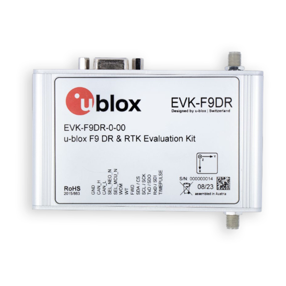
- Page 1 EVK-F9DR Evaluation kit User guide Abstract This document describes the structure and use of the EVK-F9DR evaluation kit and provides information for evaluating and testing the automotive u-blox F9 multi-band dead reckoning technology. UBX-23007618 - R01 C1-Public www.u-blox.com...
-
Page 2: Document Information
EVK-F9DR - User guide Document information Title EVK-F9DR Subtitle Evaluation kit Document type User guide Document number UBX-23007618 Revision and date 13-Nov-2023 Disclosure restriction C1-Public This document applies to the following products: Product name Type number Firmware version PCN reference... -
Page 3: Table Of Contents
EVK-F9DR - User guide Contents Document information ..........................2 Contents ................................3 Introduction ............................. 5 1.1 Highlights ..............................5 1.2 Kit contents ..............................5 1.3 System requirements ..........................5 Device description ..........................6 2.1 USB................................. 6 2.2 UART ................................6 2.3 Antenna ................................. - Page 4 EVK-F9DR - User guide 5.4.2 RealTerm ............................19 5.5 Updating the MCU firmware ........................20 Appendix ............................... 21 CAN termination ..........................21 CAN configuration examples ......................21 B.1 Wheel tick configurations ........................21 B.1.1 Two rear-wheel ticks and direction ....................21 B.1.2 Single tick and direction ........................22 B.2 Speed configurations ..........................23...
-
Page 5: Introduction
EVK-F9DR - User guide Introduction The EVK-F9DR can be used to test and evaluate all u-blox products based on the u-blox F9 multi-band GNSS dead reckoning technology. The evaluation kit (EVK) is equipped with the ZED-F9K module pre- flashed with the LAP 1.30 firmware, and allows out-of-the-box performance and feature evaluation of the following products: •... -
Page 6: Device Description
EVK-F9DR - User guide Device description 2.1 USB A USB-C connector is featured for data communication and power supply. USB drivers are installed automatically through Windows update. 2.2 UART The unit includes an RS-232 port which can be dynamically connected to the UART of the ZED-F9K, the NEO-D9S, or the onboard MCU. -
Page 7: 10-Pin Rear Connector
EVK-F9DR - User guide SEL_MCU_N Pull-down signal for enabling UART communication with the MCU TIME_MARK_J2 Time mark input Wake-on-motion signal output GND_A Ground for speed and direction inputs 5 – 24 V Wheel tick pulse input GND_A Ground for speed and direction inputs 5 –... -
Page 8: Backup Power Supply
EVK-F9DR - User guide Description Solid blue The device is powered on with no GNSS fix. The LED flashes one pulse per second during a GNSS fix. Flashing blue The time pulse signal is configurable, see the Interface description [2] for details. -
Page 9: Getting Started
EVK-F9DR - User guide Getting started This chapter works as a simple step-by-step guide for setting up the device and using it for evaluation in an automotive application using u-blox sensor fusion technology. The simplest setup uses Untethered Dead Reckoning (UDR) and relies solely on the ZED-F9K module. -
Page 10: Adr Setup (Optional)
EVK-F9DR - User guide ☞ Refer to the ZED-F9K documentation ([1], [2]) for a full description of the receiver configuration. 3.2 ADR setup (optional) To evaluate the ADR performance and features of the LAP firmware, include the following steps in the setup. -
Page 11: Testing The Receiver
EVK-F9DR - User guide Once the calibration is at a sufficient level, the receiver starts using the sensors in navigation and the fusion filter status in the ESF-STATUS shows “ FUSION ”. The receiver keeps continuously calibrating the sensors in the background to improve the quality of the solution. - Page 12 EVK-F9DR - User guide Figure 2: u-center log playback controls UBX-23007618 - R01 Getting started Page 12 of 33 C1-Public...
-
Page 13: Rtk Setup
EVK-F9DR - User guide RTK setup To achieve accurate RTK performance, the receiver needs a constant stream of correction data, which can be obtained from correction data providers via NTRIP or MQTT protocols. Application software is needed to fetch the data from the provider's server and send it to the receiver through serial ports. -
Page 14: Setting Up Mqtt Client In U-Center
EVK-F9DR - User guide The status bar at the bottom of the u-center window shows the service status for monitoring and debugging. The connection symbol turns green when authentication is successful, and the service is connected. Figure 4: u-center status bar To see more information about the NTRIP client's operation, click the connection symbol. -
Page 15: Monitoring Rtk Status
EVK-F9DR - User guide 4. Check the box to “Subscribe to key topic”. 5. Check the box to “Subscribe to AssistNow topic”. 6. Check the box to “Subscribe to data topic”. 7. Select the data topic using the drop-down menu suitable for the region of operation. - Page 16 EVK-F9DR - User guide Figure 8: RTK status in u-center In open sky scenarios, if the receiver achieves a fixed state in less than two minutes, it indicates that the receiver, antenna, and correction service are compatible and functioning properly.
-
Page 17: Configurable Can Interface
EVK-F9DR - User guide Configurable CAN interface ☞ This chapter only applies to the ADR operating mode and can be ignored for UDR. The device has a configurable high-speed CAN (ISO 11898-2) interface. The on-board MCU converts the configured CAN messages into UBX-ESF-MEAS messages which are sent to the receiver via I2C. -
Page 18: Configuration Parameters
EVK-F9DR - User guide Figure 9: C100 MSG tool The numbers in the list below refer to Figure 9: • 1: Select the blue buttons in the middle to generate messages. • 2: Fill these fields for CONFIG SET messages. -
Page 19: Connections
EVK-F9DR - User guide 5.4.1 Connections 1. Connect the pin SEL_MCU_N to the GND pin. 2. Connect a PC to the MCU via RS-232 cable or the front connector UART pins. 5.4.2 RealTerm 3. Select the port associated with the UART connection in the Port tab. -
Page 20: Updating The Mcu Firmware
EVK-F9DR - User guide 6.6. Send the CONFIG GET message. 6.7. A dialog similar to the one shown below is displayed and can be used to validate the configurations. ☞ A configuration entry can be overwritten by sending a new CONFIG SET message with the same unit and source. -
Page 21: Appendix
EVK-F9DR - User guide Appendix A CAN termination The CAN bus is terminated by including the jumper marked in the image below. The jumper is included by default. If the termination needs to be removed, open the enclosure and remove the jumper. -
Page 22: Single Tick And Direction
EVK-F9DR - User guide byte/bit The following CONFIG SET messages are generated for this configuration: • RR: 0x43 0xa2 0x11 0x13 0x03 0x23 0x01 0x00 0x00 0x08 0x00 0x28 0x10 0x00 0x00 0x00 0x00 0xff 0xff 0xe8 0x03 0x34 0x01 0xa9 0xa8 •... -
Page 23: Speed Configurations
EVK-F9DR - User guide B.2 Speed configurations B.2.1 Two rear wheels and direction This configuration uses speed from two rear wheels and a separate direction signal. The configuration entries are described in the tables below. Startbit Length Byte order Value type... - Page 24 EVK-F9DR - User guide The following CONFIG SET messages are generated for this configuration: • speed: 0x43 0xa2 0x11 0x13 0x03 0x23 0x01 0x00 0x00 0x08 0x00 0x18 0x08 0x00 0x00 0x00 0x00 0xff 0x00 0xe8 0x03 0x4a 0x00 0xa7 0xc0 •...
-
Page 25: Signed Speed
EVK-F9DR - User guide B.2.3 Signed speed This configuration uses a signed speed signal from both rear wheels. The configuration entries are described in the tables below. Startbit Length Byte order Value type Factor Offset Unit Source big-endian signed 0.01 -327.68... -
Page 26: C Step-By-Step Example
EVK-F9DR - User guide C Step-by-step example This step-by-step guide uses the example from section B.1.1. Assumptions: • User is familiar with u-center. • USB is used for powering the device and for the u-center interface. • Odometer sensor measurements are provided from the vehicle CAN bus via CAN_H and CAN_L pins on the front connector. - Page 27 EVK-F9DR - User guide Configuring the CAN interface in RealTerm 5. Open RealTerm. 6. Select the Port tab. 7. Select the PC port corresponding to the MCU UART. 8. Set baud rate to 115200. 9. Restart the EVK. 10. MCU startup dialog should appear in the terminal.
- Page 28 EVK-F9DR - User guide 11. Use the MSG tool to generate the CONFIG SET messages. Rear-right wheel tick: Rear-left wheel tick: Direction: The following CONFIG SET messages are generated for this configuration: • RR: 0x43 0xa2 0x11 0x13 0x03 0x23 0x01 0x00 0x00 0x08 0x00 0x28 0x10 0x00 0x00 0x00 0x00 0xff 0xff 0xe8 0x03 0x34 0x01 0xa9 0xa8 •...
- Page 29 EVK-F9DR - User guide UBX-23007618 - R01 Appendix Page 29 of 33 C1-Public...
-
Page 30: D Schematic
EVK-F9DR - User guide D Schematic UBX-23007618 - R01 Appendix Page 30 of 33 C1-Public... - Page 31 EVK-F9DR - User guide UBX-23007618 - R01 Appendix Page 31 of 33 C1-Public...
- Page 32 EVK-F9DR - User guide UBX-23007618 - R01 Appendix Page 32 of 33 C1-Public...
-
Page 33: Ubx-23007618 - R01
EVK-F9DR - User guide Related documentation ZED-F9K Integration manual, UBX-20046189 u-blox F9 LAP 1.30 Interface Description, UBX-22005157 ZED-F9L Integration manual, UBX-23006075, NDA required u-blox F9 DBD 1.30 Interface Description, UBX-23006359, NDA required C101-D9C User guide, UBX-21009111 NEO-D9S and ZED-F9 configuration, Application Note,...
Need help?
Do you have a question about the EVK-F9DR and is the answer not in the manual?
Questions and answers