
Related Manuals for TKO 522DBS


Summary of Contents for TKO 522DBS
- Page 1 DELUXE HEAVY BAG STAND W/ PLATFORM Model 522DBS Owner’s Manual V2.0—06.2012 www.tko.com...
- Page 2 THIS PAGE INTENTIONALLY LEFT BLANK...
- Page 3 Hours: Monday-Friday 8:30am to 4:30pm CT © Copyright 2011, TKO Sports Group USA Limited. All rights reserved. TKO Sports Group USA Limited. 4660 Pine Timbers, Suite 198, Houston, TX 77041 Phone + 713-895-9270 Fax + 713-934-8495 www.tko.com...
- Page 4 FRAME. TKO warrants this product to be free from defects in materials and workmanship for a period of 1 year from date of purchase, provided the product is used for its intended purpose, and provided the product has not been subjected to obvious abuse, misuse or neglect.
-
Page 5: Usage Instructions
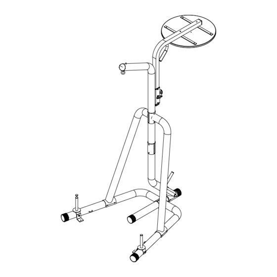
TKO recommends using only TKO brand Heavy bag TKO recommends that you use a heavy bag with a tie-down. Hang your heavy bag from the assembled eye bolt (25) using the hardware provided with your heavy bag. The eye bolt (25) is intentionally left open-ended to help hang your bag. - Page 6 Model # 522DBS Product Diagram...
-
Page 7: Exploded Diagram
Exploded Diagram EXPLODED DIAGRAM PLEASE DO NOT RETURN TO STORE, CALL OUR CUSTOMER SERVICE DEPARTMENT FIRST AT 1-866-856-3488 or 713-895-9270... -
Page 8: Parts List
PARTS LIST Parts List Part Numbers & Description 1L. Left Base Stabilizer (1pc) 1R. Right Base Stabilizer (1pc) 2. Center Base Frame (1pc) 3. Heavy Bag Angle Support Tube (1pc) 4L. Left Angle Support (1pc) 4R. Right Angle Support (1pc) 5. - Page 9 Assembly ASSEMBLY INSTRUCTIONS Note: Clean up an area at least 6’ by 6’ and a ceiling height of 7’3” high. Before starting assembly remove all parts and hardware from the carton and ensure you have everything according to the list. Do not tighten nuts and bolts until you have completed all the steps.
- Page 10 Assembly ASSEMBLY INSTRUCTIONS STEP 2. Place the Mounting Bracket of the Curved Lower Upright (5) over the Center Base Frame. Aligning the bolt holes with the second set of holes on the Center Base Frame, secure with two Hex Bolts (23), four Washers (21), and two Nylon Locknuts (22).
- Page 11 Assembly ASSEMBLY INSTRUCTIONS STEP 3 Insert the Heavy Bag Eye Bolt (25) into the end bolt hole on the Heavy Bag Angle Support Tube (3). Attach from the top using one Washer (21) and one Nylon Locknut (22) and tighten, however leave the bolt just loose enough that it can turn around in the bolt hole.
- Page 12 Assembly ASSEMBLY INSTRUCTIONS STEP 4 Slide the Heavy Bag Support Tube (3) between the Mounting Bracket of the Left and Right Angle Supports, and then insert into the top of the Curved Lower Upright as shown. The Heavy Bag Support should be facing the front of the Stand. Align the holes on the Brackets and the Heavy Bag Support Tube and secure using two Hex Bolts (23), four Washers (21), and two Nylon Locknuts (22).
- Page 13 Assembly ASSEMBLY INSTRUCTIONS STEP 5 Install two Reinforcement Plates (35) around the connection position of the Curved Lower Upright and the Heavy Bag Support Tube. Aligning the bolt holes, secure using two Hex Bolts (23), four Washers (21), and two Nylon Locknuts (22). PLEASE DO NOT RETURN TO STORE, CALL OUR CUSTOMER SERVICE DEPARTMENT FIRST AT 1-866-856-3488 or 713-895-9270...
- Page 14 Assembly ASSEMBLY INSTRUCTIONS STEP 6 Attach the Swivel hook (13), Swivel Kit (14), and Swivel Plastic Cushion (38) to the Speed Bag Platform (11), with 4 Phillips Screws (10), 4 Washers (20), and 4 Lock Nuts (19). (This has been pre-assembled in factory). Tighten it securely before you use it. Mount each Speed Bag Platform Support Plate (30) to the Speed Bag Platform (11) using two Screws (12), two Washers (34), and two Nylon Locknuts (33).
- Page 15 Assembly ASSEMBLY INSTRUCTIONS STEP 7 Attach the Speed Bag Platform (11) to the Speed Bag Support Tube (8) using two Screws (32), two Washers (37), two Washers (21), and two Nylon Locknuts (22) as shown. PLEASE DO NOT RETURN TO STORE, CALL OUR CUSTOMER SERVICE DEPARTMENT FIRST AT 1-866-856-3488 or 713-895-9270...
- Page 16 Assembly ASSEMBLY INSTRUCTIONS STEP 8 Loosen the Spring Pin (9) and T-Lock Pin (18), and slide the Speed Bag Support Tube into the square holder on the rear of the Heavy Bag Angle Support Tube. To adjust the height of the Speed Bag Platform: Loosen the T-Lock Pin, place one hand on the handle at the bend of the Speed Bag Support Tube and use the other hand to pull the Spring Pin, adjust the Platform to the desired height.
- Page 17 Assembly ASSEMBLY INSTRUCTIONS STEP 9 Set each of the Rod-Bolt Down Weight Horns (6) on the end of the Base Stabilizer as shown. Push one Hex Bolt (36) and one Washer (34) through one side of the Weight Horn Bracket of the Base Stabilizer and out through the opposite side of the Weight Horn Bracket, then Anchor Bracket (29).
- Page 18 Assembly ASSEMBLY INSTRUCTIONS STEP 10 Insert the Sit-Up Rod (26) into the hole on the lower section of the Curved Lower Upright as shown. Align the hole on the Sit-Up Rod with the hole on the rear of the Curved Lower Upright. Secure with the threaded Bolt on the end of the Rear Weight Horn (07).
- Page 19 Assembly ASSEMBLY INSTRUCTIONS STEP 11 Tighten all nuts and bolts with wrenches at this time. PLEASE DO NOT RETURN TO STORE, CALL OUR CUSTOMER SERVICE DEPARTMENT FIRST AT 1-866-856-3488 or 713-895-9270...
Need help?
Do you have a question about the 522DBS and is the answer not in the manual?
Questions and answers