
Related Manuals for TKO 866HP


Summary of Contents for TKO 866HP
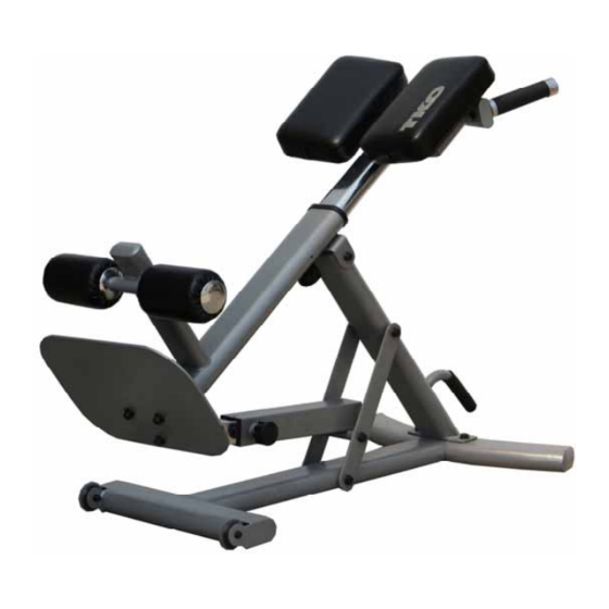
- Page 1 HYPER EXTENSION Model 866HP TKO SPORTS GROUP USA LIMITED 7354 Denny Road #100 Houston, TX77040...
-
Page 2: Important Safety Instructions
IMPORTANT SAFETY INSTRUCTIONS TKO Fitness products are designed and manufactured to the highest standards in order to provide you with years of great workouts. We proudly stand behind all our products with the best customer service in the fitness industry. If you have any question or need assistance please contact us at: Customer Service: customerservice@tko.com... -
Page 3: Exploded Drawing
EXPLODED DRAWING... -
Page 4: Parts List
PARTS LIST No. Description Q’ty No. Description Q’ty Base Frame Foam Grip Base Frame Stabilizer End Cap 60mm Square Angle Support Frame End Cap 50mm Square Angle Brace Name Plate Handlebar Rubber Floor Pad Rivet Φ3.2x10 mm Thigh Pad Support Frame Angle Selector Outer Post Flat washer for M12 Bolt Angle Selector Inner Post... -
Page 5: Assembly Steps
ASSEMBLY STEPS Step 1 Attach the Base Frame Stabilizer (2) to the Base Frame (1), using 2 Hex Bolts (35), and 2 Flat Washers (32). Step 2 Attach the Angle Support Frame (3) to the Base Frame Assembly, using 2 Hex Bolts (38) and 2 Flat washers (32). - Page 6 Step 3 Install the Angle Brace (4) to the Angle Support Frame (3) and Base Frame Assembly using 4 Metal Bushings (17) 4 Flat Washers (32), 2 Hex Bolts (34) and 2 Lock Nuts (33). Attach the Angle Selector Outer Post (7) to the middle hole in the Angle Brace (4), using 2 Metal Bushings (17), 2 Flat Washers (32), one Hex Bolt (34) and one Lock Nut (33).
- Page 7 Step 4 Connect the Main Support Frame (9) to the top of the Angle Support Frame (3), using 2 Metal Bushings (17), 2 Flat Washers (32), one Hex Bolt (34) and one Lock Nut (33). Connect the other end of the Main Support Frame (1) to the Angle Selector Assembly, using 2 Metal Bushings (17), 2 Flat Washers (32), one Hex Bolt (34) and one Lock Nut (33).
- Page 8 Step 5 Insert the Foam Roller Tube (11) to the hole in of the Main Support Frame (1), then slide the Foam Roller Inner Cap (14), the Foam Roller (25) and the Foam Roller Outer Cap (13) onto each side of the Foam Roller Tube (11), secure the Outer Cap with 2 Allen Bolts (42), and Plug the Rubber Plug (47) into the hole in the Outer Cap (13).
- Page 9 Step 6 Attach the Thigh Pads Support Frame (6) to the Thigh Pads Adjustable Post (10), using 2 Hex Bolts ( 37) and 2 Flat Washers (32). Tighten these 2 bolts securely with wrenches. Insert the Handlebar (5) to the Thigh Pads Support Frame (6), tighten with 2 Allen Bolts (41) and 2 Flat Washers (43).
- Page 10 Step 8 Insert the Thigh Pads Adjustable Post Assembly into the Main Support Frame. The Spring Loaded Knob is designed with a locking feather. When making adjustments, loosen the Knob by turning the knob counter-clockwise 3 to 4 turns. Pull the knob (33) outward and slide the Thigh Pads Support Frame assembly to a proper position that is most comfortable for you, then release the knob making sure the lock pin drops into the hole on the Thigh Pads support frame (24.
Need help?
Do you have a question about the 866HP and is the answer not in the manual?
Questions and answers