Table of Contents
Advertisement
Quick Links
Advertisement
Table of Contents

Related Manuals for TKO AirRaid


Summary of Contents for TKO AirRaid
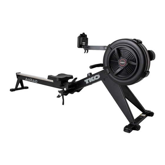
- Page 1 Version 2 AirRaid Rower Owner’s Manual...
-
Page 2: Table Of Contents
TABLE OF CONTENTS Safety Instructions ........2 Maintenance ..........19 Storage ............21 Before You Begin ......... 3 Equipment Warning, Warning Labels ..4 Product Parts Drawing ....... 22 Hardware Identification Chart ....5 Parts List............23 Assembly Instructions ....... 6 Computer Instructions ....... -
Page 3: Before You Begin
BEFORE YOU BEGIN convenient and simple method to begin your Thank you for choosing the ROWER. We take journey of getting your body in shape and achieving great pride in producing this quality product and a happier and healthier lifestyle. hope it will provide many hours of quality exercise Before reading further, please review the to make you feel better, look better, and enjoy... -
Page 4: Equipment Warning, Warning Labels
EQUIPMENT WARNING, WARNING LABELS This chart is provided to help identify the warning, caution, and notice labels on the ROWER. Please take a moment to familiarize yourself with all of the warning, caution, and notice labels. Label is larger than actual size WARNING LABEL... -
Page 5: Hardware Identification Chart
HARDWARE IDENTIFICATION CHART This chart is provided to help identify the fasteners used in the assembly process. Place the washers or the ends of the bolts or screws on the circles to check for the correct diameter. Use the small scale to check the length of the bolts and screws. -
Page 6: Assembly Instructions
ASSEMBLY INSTRUCTIONS STEP 1 First, take out the packing materials Styrofoam (A) and Styrofoam (B). Then flip them over so the sides with carved letter are facing up. Take the Main Frame (175 ) out from the carton and put it on both Styrofoam (A & B) as picture shown. The Right and Left Fan Shrouds (43 & 44) should be placed in the groove of Styrofoam (B). - Page 7 STEP 2 Turn the main assembly of the ROWER upside down and place it in the packing material Styrofoam (A & B) to avoid damage of housing. Attach Left and Right Support Legs (7 & 8) to the Main Frame (175) using: 4 PCs of M8x12mm Socket Head Cap Screw (81) and M8 Flat Washer (79).
- Page 8 ASSEMBLY INSTRUCTI NS STEP 4 Lift up the Main Frame (175). Insert the Pedal Shaft 16mm (139) and Pedal Shaft 12mm (140) through right and left Pedal Support Plate (177) and Main Frame (175). Attach Pedal Support Plate (177) on Main Frame (175) by using Socket Head Cap Screw, M8X20 (173) and Foot Pedal End Cap (178).
- Page 9 ASSEMBLY INSTRUCTIONS STEP 6 Lift up the Lower Console Monitor Post (135). Attach the Lower Console Monitor Post (135) on Left/Right Side Cover (57/58) by using Phillips Pan Head Screw, M6X12mm (131). NOTE: Fully tighten bolts at end of this step.
- Page 10 COMPUTER INSTRUCTIONS STEP 7 Attach the Console Monitor (19) to the Console Mounting Bracket (179 ) by using M8X75mm Button Head Cap Screw (78), M8 Flat Washer (79), and M8 Nylon Lock Nut (80). STEP 8 Connect Sensor Cable (23) into the back of the Console Monitor (19a).
-
Page 11: Computer Instructions
COMPUTER INSTRUCTIONS Front View Back View Smartphone Holder Ba�eries Cover Sensor Cable Plugin Operates on 2 size C Your ROWER u�lizes an air fan system to create resistance for your workout. We recommend that you use this computer console to vary your workout from session to session and note your progress toward your fitness goals. - Page 12 COMPUTER INSTRUCTIONS Func�on Bu�ons BACK BUTTON: - When selec�ng the programs, press the bu�on to return to the previous program. - When you finish a running program, press the bu�on to jump into the IDEL mode. SELECT BUTTON: - In IDLE mode, press and release SELECT to cycle through each program op�on.
- Page 13 COMPUTER INSTRUCTIONS Console Display STROKE RATE - Display the current stroke per minute during exercise. TIME TIME/500 M - The lightened up semi-circle equals to the stroke rate that displayed in numbers. The - Total workout �me - Time/500m is the es�mated �me more grids it shows, the higher your stroke for reaching distance of 500 rate is.
- Page 14 COMPUTER INSTRUCTIONS PROGRAMS The console monitor has 8 programs. Press SELECT to change workout programs according to the following sequence. Quick Start Program > Distance Countdown > Time Countdown > Calories Countdown > Game > 20/10 Interval > 10/20 Interval > 10/10 Customize Interval 1.
- Page 15 COMPUTER INSTRUCTIONS PROGRAMS The console monitor has 8 programs. Press SELECT to change workout programs according to the following sequence. Quick Start Program > Distance Countdown > Time Countdown > Calories Countdown > Game > 20/10 Interval > 10/20 Interval > 10/10 Customize Interval 5.
- Page 16 COMPUTER INSTRUCTIONS Please make sure the console is ac�vated in order BLUETOOTH CONNECTION to proceed Bluetooth connec�on with your smart- phone or tablet devices. AVAILABLE APPS Kinomap D-fit ENTER SELECT BACK STOP FTMS PROTOCOL The “bt” will be displayed and switch between pulse when connec�ng to an app.
-
Page 17: Operational Instructions
OPERATIONAL INSTRUCTIONS LOAD ADJUSTMENT There is a Damper (42) built into the Right Fan Shroud (43). Indicator Move the Indicator in the Damper (42) to point to the numbers on the Right Fan Shroud (43) to adjust the load. There are settings will provide the lowest resistance. - Page 18 OPERATIONAL INSTRUCTIONS USING THE SMARTPHONE HOLDER The Smartphone Holder 156 ) can move up and down. Move up the Smartphone Holder 156 , then slide the Cell Phone into the gap between the Smartphone Holder 156 and the Console Monitor (19). Move down the Smartphone Holder 156 to clip the Cell Phone in position.
-
Page 19: Maintenance
MAINTENANCE The safety and integrity designed into the ROWER can only be maintained when the ROWER is regularly examined for damage and wear. Special attention should be given to the following: 1. Pull on the Handlebar (3) and verify that the Magnetic System provides tension and the seat travel is smooth and stable. - Page 20 3. Position the Main Frame Assembly (175) as shown in the illustration. Slid the Bottom Cover (70) back into the Main Frame (175 ).Press the Main Frame Top Cap (68) into the Main Frame (175). CONSOLE MONITOR POST ADJUSTMENT If the Lower Console Monitor Post (135) is getting loosen, please tighten Socket Head Cap Screw, M6x16mm (99) by using Allen Wrench (5mm).
-
Page 21: Storage
STORAGE 1. To store the ROWER, simply keep it in a clean dry place. 2. To avoid damage to the electronics, remove the batteries from the Console Monitor (19) before storing the ROWER for one year or more. 3. Move the ROWER with the Transport Wheels (66) on the Front Stabilizer (4). Lift the Rear Stand of the Rail Frame (2) to move the ROWER. -
Page 22: Product Parts Drawing
PRODUCT PARTS DRAWING FRONT 31 29 BACK... -
Page 23: Parts List
PARTS LIST PART# DESCRIPTION... - Page 26 Caution Label Stopper bracket Manual Phillips Head Screw, M6x30mm (Half Thread) Lock Washer, M6 Nylon Lock Nut, M6 Philips Pan Head Self-Tapping Screw Phillips Pan Head Screw, M6X12mm Upper Console Monitor Post Lower Console Monitor Post Screw Shaft Sink Pad Rotation Sleeve Padel Shaft, 16mm...
- Page 27 Padel Shaft, 12mm Smartphone Holder Bungee Cord of Smartphone Holder Left Joint Cover Right Joint Cover Console EVA Pad Smart Phone Holder EVA Pad Phillips Pan Head Self-Tapping Screw, ST4.2X35mm Socket Head Cap Screw, M8X20 Seat Carriage Cover...
Need help?
Do you have a question about the AirRaid and is the answer not in the manual?
Questions and answers