Advertisement
Quick Links
Advertisement

Related Manuals for TKO 865CB-B


Summary of Contents for TKO 865CB-B
- Page 1 ADJUSTABLE AB/CRUNCH BENCH Model 865CB-B Owner’s Manual V2.0—06.2012 www.tko.com...
- Page 2 THIS PAGE INTENTIONALLY LEFT BLANK...
- Page 3 Hours: Monday-Friday 8:30am to 4:30pm CT © Copyright 2011, TKO Sports Group USA Limited. All rights reserved. TKO Sports Group USA Limited. 4660 Pine Timbers, Suite 198, Houston, TX 77041 Phone + 713-895-9270 Fax + 713-934-8495 www.tko.com...
-
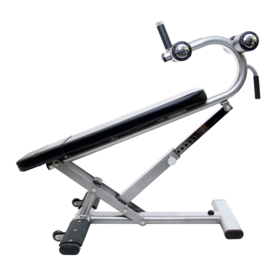
Page 4: Product Diagram
Product Diagram Parts list ✚ Description Q’ty Description Base Frame Allen Bolt M8x45mm Angle Support Flat Washer for M8 Bolt Angle Support Bracket Lock Nut for M8 Bolt Angle Selector Outer Post Hex Bolt M12x145mm Angle Selector Inner Post Hex Bolt M12x130mm Back Pad Support Frame Carriage Bolt M12x70mm Foam Roller Tube... -
Page 5: Exploded Diagram
Exploded diagram ✚ Exploded Diagram... - Page 6 Parts List Parts list ✚ Description Q’ty Description Q’ty Base Frame Allen Bolt M8x45mm Angle Support Flat Washer for M8 Bolt Angle Support Bracket Lock Nut for M8 Bolt Angle Selector Outer Post Hex Bolt M12x145mm Angle Selector Inner Post Hex Bolt M12x130mm Back Pad Support Frame Carriage Bolt M12x70mm...
- Page 7 Assembly Assembly ✚ Step 1 Attach the Base Frame Stabilizer (12) to the Base Frame (1), using 2 Hex Bolts (31) and 2 Flat Washers (26). Please do not tighten these nuts and bolts until Step 3. Step 2 Attach the Angle Support (2) to the Base Frame Stabilizer (12), using 2 Carriage Bolts (32) from the bottom, 2 Flat Washers (26) and 2 Lock Nuts (25).
- Page 8 Assembly Step 3 Attach the Angle Support Bracket (3) to the Base Frame (1) and Angle Support (2), using 2 Hex Bolts (30), 4 Metal Bushing (18), 4 Flat Washers (26) and 2 Lock Nuts (25). Insert the Angle Selector Outer Tube (4) between the Angle Support Bracket (3), secure it using a Hex Bolt (30), 2 Metal Bushing (18), 2 Flat Washers (26), and one Lock Nut (25).
- Page 9 Assembly Step 4 Attach the Back Pad (9) to the Back Pad Support Frame (6), using 6 Allen Bolts (34) and 6 Flat Washers (33). Tighten all 6 Allen bolts using Allen wrench (included). Step 5 Insert the Foam Roller Tube (7) into the hole in the Back Pad Support Frame (6), Slide the Foam Roller Inner Caps (10), Foam Rollers (16) and the Foam Roller Outer Caps (11) onto the Tube (7).
Need help?
Do you have a question about the 865CB-B and is the answer not in the manual?
Questions and answers