Table of Contents
Advertisement
Quick Links
Advertisement
Table of Contents

Related Manuals for TKO 866HP-B


Summary of Contents for TKO 866HP-B
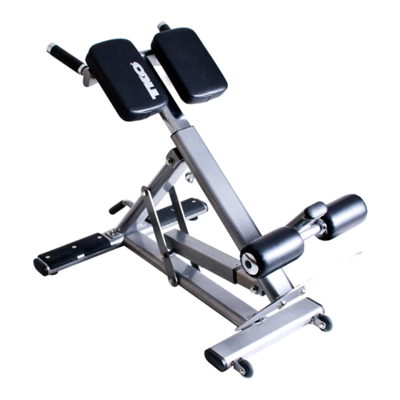
- Page 1 HYPER EXTENSION Model 866HP-B Owner’s Manual V2.0—06.2012 www.tko.com...
- Page 2 THIS PAGE INTENTIONALLY LEFT BLANK...
- Page 3 Hours: Monday-Friday 8:30am to 4:30pm CT © Copyright 2011, TKO Sports Group USA Limited. All rights reserved. TKO Sports Group USA Limited. 4660 Pine Timbers, Suite 198, Houston, TX 77041 Phone + 713-895-9270 Fax + 713-934-8495 www.tko.com...
-
Page 4: Product Diagram
Product Diagram IMPORTANT SAFETY INSTRUCTIONS TKO Fitness products are designed and manufactured to the highest standards in order to provide you with years of great workouts. We proudly stand behind all our products with the best customer service in the fitness industry. If you have any question or need assistance please contact us at: Customer Service: customerservice@tko.com... -
Page 5: Exploded Diagram
EXPLODED DRAWING Exploded Diagram... -
Page 6: Parts List
PARTS LIST Parts List No. Description Q’ty No. Description Q’ty Base Frame Rubber Floor Pad Base Frame Stabilizer Rivet √3.2x10 mm Angle Support Frame Flat washer for M12 Bolt Angle Brace Lock Nut for M12 Bolt Handlebar Hex Bolt M12x145mm Thigh Pad Support Frame Hex Bolt M12x130mm Angle Selector Outer Post... -
Page 7: Assembly Steps
Assembly ASSEMBLY STEPS Step 1 Attach the Base Frame Stabilizer (2) to the Base Frame (1), using 2 Hex Bolts (35), and 2 Flat Washers (32). Step 2 Attach the Angle Support Frame (3) to the Base Frame Assembly, using 2 Hex Bolts (57) 2 Flat Washers (22) and 2 Lock Nuts (33). - Page 8 Assembly Step 3 Install the Angle Brace (4) to the Angle Support Frame (3) and Base Frame Assembly using 4 Metal Bushings (17) 4 Flat Washers (32), 2 Hex Bolts (34) and 2 Lock Nuts (33). Attach the Angle Selector Outer Post (7) to the middle hole in the Angle Brace (4), using 2 Metal Bushings (17), 2 Flat Washers (32), one Hex Bolt (34) and one Lock Nut (33).
- Page 9 Assembly Step 4 Connect the Main Support Frame (9) to the top of the Angle Support Frame (3), using 2 Metal Bushings (17), 2 Flat Washers (32), one Hex Bolt (34) and one Lock Nut (33). Connect the other end of the Main Support Frame (1) to the Angle Selector Assembly, using 2 Metal Bushings (17), 2 Flat Washers (32), one Hex Bolt (34) and one Lock Nut (33).
- Page 10 Assembly Step 5 Insert the Foam Roller Tube (11) to the hole in of the Main Support Frame (1), then slide the Foam Roller Inner Cap (14), the Foam Roller (25) and the Foam Roller Outer Cap (13) onto each side of the Foam Roller Tube (11), secure the Outer Cap with 2 Allen Bolts (42), and Plug the Rubber Plug (47) into the hole in the Outer Cap (13).
- Page 11 Assembly Step 6 Attach the Thigh Pads Support Frame (6) to the Thigh Pads Adjustable Post (10), using 2 Hex Bolts (37) and 2 Flat Washers (32). Tighten these 2 bolts securely with wrenches. Insert the Handlebar (5) to the Thigh Pads Support Frame (6), tighten with 2 Allen Bolts (41) and 2 Flat Washers (43).
- Page 12 Assembly Step 7 Attach the Thigh Pads (23) to the Thigh Pads Support Frame Assembly, using 4 Allen Bolts (39) and 4 Flat Washers (43). Tighten these 4 bolts with Allen wrench (included).
- Page 13 Assembly Step 8 Insert the Thigh Pads Adjustable Post Assembly into the Main Support Frame. The Spring Loaded Knob is designed with a locking feather. When making adjustments, loosen the Knob by turning the knob counter-clockwise 3 to 4 turns. Pull the knob (18) outward and slide the Thigh Pads Support Frame assembly to a proper position that is most comfortable for you, then release the knob making sure the lock pin drops into the hole on the Thigh Pad Adjustable Post (10).
Need help?
Do you have a question about the 866HP-B and is the answer not in the manual?
Questions and answers