Table of Contents
Advertisement
Quick Links
Advertisement
Table of Contents
Troubleshooting

Related Manuals for SKF Baker AWA-IV


Summary of Contents for SKF Baker AWA-IV
- Page 1 User manual SKF Static Motor Analyzer Baker AWA-IV...
- Page 3 SKF USA, Inc. SKF USA, Inc. assumes no liability for damages consequent to the use of this product. No part of this document may be reproduced in part or in full by any means such as photocopying, photographs, electronic recording, videotaping, facsimile, etc., without written permission...
- Page 4 (the test equipment version) and to one specific copy of the desktop version of the Baker AWA-IV software provided in CD form for use on the user’s separate computer (the desktop version). The term documentation refers to the associated instructions and reference materials.
- Page 5 In no case shall SKF USA, Inc., or its agents be liable for any loss of data, lost profits, special, incidental, consequential, indirect, or other similar damages arising from breach of contract, negligence or any other legal theory.
- Page 6 The warranty is void if the Baker AWA-IV is shipped without shock absorbing packing material. If the Baker AWA-IV fails, whether it is under warranty or not, call the SKF electric motor condition monitoring products service department before returning the unit for repair.
- Page 7 Notices virus-free. Before inserting any disks into the disk drive or connecting the Baker AWA-IV to a computer network, scan all disks for viruses. Trademarks All other trademarks, service marks or registered trademarks appearing in this manual are the trademarks, service marks or registered trademarks of their respective owners.
- Page 8 EN 61000-4-11 I, the undersigned, hereby declare that the equipment specified above conforms to the above Directives and Standards. Signature: Printed Name: Mike Teska Title: Engineering Manager, SKF USA, Inc. Electric Motor Condition Monitoring SKF Static Motor Analyzer—Baker AWA-IV User Manual...
-
Page 9: Table Of Contents
General operation, maintenance, and service information ..........8 Unpacking the unit ........................ 8 Power pack lifting and shipping ..................9 Operating and shipping positions ..................10 3 Baker AWA-IV instrument overview Baker AWAIV 2kV/4kV model front panel ................11 AWAIV 6kV/12kV model front panel.................13 4 Baker AWA-IV software overview Starting the software ......................15... - Page 10 Using multiple databases ....................64 Data Transfer feature ......................65 Archiving a database ......................69 Restoring a database ......................70 Converting an older database ...................72 6 Setting up the Baker AWA-IV tester Printer configuration ......................75 Provided memory key ......................75 Use of footswitch .........................75 7 Test procedures Recommended testing sequence ..................79...
- Page 11 Quality control ........................102 Motor troubleshooting ....................102 Field coils ........................... 102 Hi L in Baker AWA-IV 2 kV and Baker AWA-IV 4 kV ............ 103 Using the Hi L technique ....................104 Fine tuning the technique ....................105 9 Motor testing theory and reference Coil resistance testing principles and theory ...............
- Page 12 Appendix C — Technical specifications and applicable standards Baker AWA-IV 2 kV and 4 kV tester specifications ............191 Baker AWA-IV 6 kV, 12 kV, and 12 kV HO tester specifications ......... 193 Applicable standards ....................... 195 Appendix D — Database definition Version 4.0 database definition ..................
- Page 13 Reference Surge waveform table— (RefSrgWaveForm) ..........217 Database Information table—(DatabaseInfo) .............. 218 Work list table—(Route) ....................218 Motor voltage class table—(MotorVoltageClasses) ............. 219 Appendix E — Baker AWA-IV specific winding faults Software fault messages....................221 Resistance failure types ....................221 DC tests failure types ....................... 222 Surge test failure types ....................
- Page 14 Table of Contents SKF Static Motor Analyzer—Baker AWA-IV User Manual...
-
Page 15: About This Manual
About this manual This manual uses the following conventions in formatting, and informational devices to help you more clearly identify specific elements and information. Formatting Interface items are set in Initial Caps and Bold. Page or window names are set in italics. File names are set in courier font. - Page 16 About this manual SKF Static Motor Analyzer—Baker AWA-IV User Manual...
-
Page 17: Safety And General Operating Information
Labels on equipment The following Danger notice label appears on all four sides of the power pack units used with the Baker AWA-IV and on the top of the Baker AWA-IV unit itself. Figure 1. High voltage warning label. -
Page 18: Safety Precautions
The general safety information presented here is for both operating and service personnel. You will find specific warnings and cautions throughout this manual where they apply. If using the equipment in any manner not specified by Baker Instrument Company, an SKF Group Company, the protection provided by the equipment may be impaired. - Page 19 NOTICE The ground-fault system on the Baker AWA-IV will render it inoperative without a proper ground. When the host Baker AWA-IV tester is connected to a power pack, an inoperable condition will also affect the power pack. SKF Static Motor Analyzer–Baker AWA-IV User Manual...
-
Page 20: Emergency Stop Button
Safety and general operating information Emergency stop button The Baker AWA-IV tester and the power packs are equipped with a red Emergency Stop (E-Stop) button on the front panel of the unit. Use it to quickly discontinue a test and to shut off power to the power pack’s high-voltage circuitry. -
Page 21: Baker Ztx E-Stop And Remote E-Stop
Safety and general operating information Baker ZTX E-stop and remote E-stop The Baker ZTX can be used with the Baker AWA-IV 6/12kV models. The Baker ZTX unit and the remote E-Stop unit are both equipped with a red Emergency Stop button. The Emergency Stop button is on top of the Baker ZTX unit and it is in the line with the status lights on the remote E-Stop accessory. -
Page 22: General Operation, Maintenance, And Service Information
2 amps AC maximum current draw. An auto-reset circuit breaker protects the unit. 220/240 VAC units 220/240 VAC input units are indicated by information on the Baker AWA-IV. These units might require you to supply an appropriate AC connector for mating to the power source. -
Page 23: Power Pack Lifting And Shipping
The power pack is shipped as indicated by the shipping labels. Inspect the units after shipping and notify carrier immediately if damaged is found. Confirm that the back panel of the power pack lists the Baker AWA-IV serial number before connecting to the power pack. -
Page 24: Operating And Shipping Positions
If the product must be shipped for any reason, the package containing the power pack must be properly labeled with “this side up” labels to ensure the instrument is shipped in the upright position. SKF Static Motor Analyzer–Baker AWA-IV User Manual... -
Page 25: Baker Awa-Iv Instrument Overview
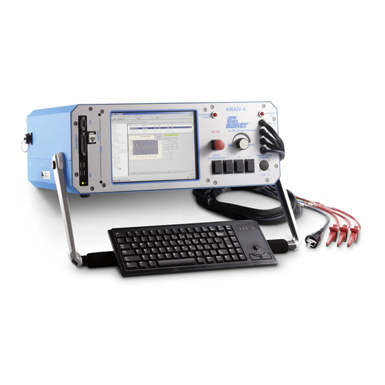
Baker AWA-IV 2 kV and 4 kV model front panel All Baker AWA-IV series testers feature a large 8-inch touch screen with a graphical user interface. The interface features a logical layout of large touch icons that improve ease of use, even with electrical gloves. - Page 26 The rate of voltage increase or decrease is set via the touch screen interface. Do not force the knob; turning the knob harder does not cause voltage to ramp any quicker and may damage the instrument. SKF Static Motor Analyzer—Baker AWA-IV User Manual...
-
Page 27: Awaiv 6Kv/12Kv Model Front Panel
Baker AWA-IV 6 kV and 12 kV model front panel All Baker AWA-IV series testers feature a large eight-inch touch screen with a graphical user interface. The interface features a logical layout of large touch icons that improve ease of use, even with electrical gloves. - Page 28 Baker AWA-IV Instrument Overview SKF Static Motor Analyzer—Baker AWA-IV User Manual...
-
Page 29: Baker Awa-Iv Software Overview
Pre-configured tests are identified by Test IDs. Pre-configured motors are identified by Motor IDs. Motor IDs are stored in the Baker AWA-IV’s database along with the Test ID to be used when testing that motor. Additional information about the motor such as manufacturer, serial number, horsepower rating, frame size, speed, operating voltage, and current are also stored in the Motor ID. -
Page 30: Creating A New Database
4) Click on the Save button. A database will be created and opened that has one default motor and the default Test IDs. At this point begin entering new motors using the Data-Nameplate tab. SKF Static Motor Analyzer—Baker AWA-IV User Manual... -
Page 31: Opening An Existing Database
It will default to the folder that has been selected in View- Options-File Locations menu item. 3) Select a database (.mdb) then click the Open button or double clicking on the desired database. Figure 10. Selecting an existing database. SKF Static Motor Analyzer—Baker AWA-IV User Manual... -
Page 32: The First Time Version 4 Software Is Used
When using Version 4 software for the first time The first time the Baker AWA-IV software is used, the Enter Test Equipment Information window will appear. Select the tester type, serial number (found on a sticker on back of unit), and customer’s tester ID (can be an asset ID). -
Page 33: Main Window
Motor ID, and Route—that facilitate browsing through the motors in the database. The right pane contains three more tabs—Data, Tests, and Trending—that help you view test data, performance of set tests, and trending mechanisms. SKF Static Motor Analyzer—Baker AWA-IV User Manual... -
Page 34: Main Menu
Databases that are open are listed just above the Exit item. Clicking on Exit closes the application. The Print menu item provides access to printing features. Figure 14. File menu. SKF Static Motor Analyzer—Baker AWA-IV User Manual... - Page 35 Motor ID. Notes within the Motor ID, or the placement of the Motor ID in the “building” and “location” folders can be used to uniquely identify each motor. Figure 15. View menu. SKF Static Motor Analyzer—Baker AWA-IV User Manual...
- Page 36 Figure 16. Database menu. Window menu The Windows menu provides you with functions for selecting which database to use (if several are open) along with options for displaying windows within your screen. Figure 17. Window menu. SKF Static Motor Analyzer—Baker AWA-IV User Manual...
- Page 37 The Tools menu provides access to other basic tools including WordPad, MS Paint, and a web archive file viewer. The Baker AWA-IV generates reports in a mhtml format (optionally); these files can be viewed used the web archive file viewer. MS WordPad can be used to view files output in Word format, and the MS Paint program is handy for annotating screen captures.
-
Page 38: Toolbar
Hovering the mouse cursor over an icon provides you with flyout tool tips that identify the icon. The Toolbar also identifies the current motor displayed in the user interface along with the number of test records currently stored in the database for the selected device/motor. Figure 20. Toolbar. SKF Static Motor Analyzer—Baker AWA-IV User Manual... -
Page 39: Tabs
It becomes the current motor. Expand a motor location by clicking on the plus sign or contract a location by clicking on the minus sign. SKF Static Motor Analyzer—Baker AWA-IV User Manual... - Page 40 The second method is to simply scroll down in the list until you spot the Motor ID you need, then double click or highlight the Motor ID and click the Display button to select the desired Motor ID. SKF Static Motor Analyzer—Baker AWA-IV User Manual...
- Page 41 2) Click on the Rename button. 3) The Route ID will be highlighted. Edit the ID as needed then click the Update button. The Update button appears when you click the Rename button. SKF Static Motor Analyzer—Baker AWA-IV User Manual...
- Page 42 Move Up or Move Down buttons found just below the list. 7) When you have finished editing a route, click on the Update List button to save your changes. SKF Static Motor Analyzer—Baker AWA-IV User Manual...
-
Page 43: Viewing Test Data
Trending. Respectively, these tabs help you view results data for a variety of tests; check the status, configure, or execute tests; and display trending graphs that chart acquired data over time. Figure 24. Right pane of Main window features Data, Tests, and Tending tabs. SKF Static Motor Analyzer—Baker AWA-IV User Manual... -
Page 44: Using The Data Tab
Application, Surge, PI, or Step/Ramp-Voltage tabs in the lower section. The view in the lower section changes depending on which bottom tab is selected. Figure 25. Data tab sections. SKF Static Motor Analyzer—Baker AWA-IV User Manual... - Page 45 Baker AWA-IV software overview Motor ID field The records stored by the Baker AWA-IV are hierarchically linked to each other. The Motor ID field serves as the primary key for linking associated records. The Motor ID is the principal means of locating and interacting with a motor’s data. Therefore, it is important to develop a naming scheme that will facilitate locating and retrieving information.
- Page 46 The Nameplate view contains the nameplate data on each motor in the database. The first field is Motor ID, which is used by the Baker AWA-IV program to uniquely identify the motor. Values must be entered in the Motor ID and the two motor location fields.
- Page 47 1) Select the desired Motor ID then click on the Del (delete) button. 2) A dialog box appears asking if the request is appropriate. If it is, click Yes. The motor and all of its test results will be deleted. SKF Static Motor Analyzer—Baker AWA-IV User Manual...
- Page 48 To change what test result is being displayed, click on the date/time in the top section of the Data tab. The Application view will then display the selected data/time’s information. SKF Static Motor Analyzer—Baker AWA-IV User Manual...
- Page 49 To print a copy of this view, click the right mouse button click anywhere on the grid and a dialog box will appear, allowing you to choose a printer and parameters for printing the grid. SKF Static Motor Analyzer—Baker AWA-IV User Manual...
-
Page 50: Data Tab-Surge View
Figure 31. Data tab—Surge view showing test results. The Surge view not only displays the surge waveforms for all leads, it also renders a view of the pulse-to-pulse Error Area Ratio (EAR). SKF Static Motor Analyzer—Baker AWA-IV User Manual... - Page 51 Click on the pp-EAR button to view the pulse-to-pulse EAR graph. The graph displays the EAR percentage between successive pulses per test lead and the tolerance used during the test. Figure 32. Pulse-to-pulse EAR example. SKF Static Motor Analyzer—Baker AWA-IV User Manual...
- Page 52 On the right side of the graph you will see data for PASS/FAIL, Test Voltage, DA/PI ratios, and four check boxes. You can use the check boxes to select the graph plot Meg-Ohm and/or Current data in one second or one-minute increments. SKF Static Motor Analyzer—Baker AWA-IV User Manual...
- Page 53 Figure 34. Step/ramp Voltage view showing current vs. voltage. NOTE The large excursion of the red real-time current line shows the motor’s charging current while ramping up voltage. The large swings of this value do not indicate an insulation problem SKF Static Motor Analyzer—Baker AWA-IV User Manual...
- Page 54 Meg-Ohm value at each end point. Figure 35. Step/Ramp Voltage view showing current vs. time. SKF Static Motor Analyzer—Baker AWA-IV User Manual...
-
Page 55: Using The Tests Tab
Test IDs, click on the Edit Test ID check box to disable Test ID editing. NOTE Leaving the Tests view will also disable the editing of test ID’s and all changes will be lost if they have not been saved. SKF Static Motor Analyzer—Baker AWA-IV User Manual... -
Page 56: Test Configuration
Baker AWA-IV software overview Test configuration The three major setup windows for configuring Baker AWA-IV tests are described below. The specific choices made in the test setup windows define the Test ID. Before editing test parameters, check the Edit Test ID box and enter your password to allow updates to the test parameters and to enable saving your changes when finished. - Page 57 Figure 38. Resistance enabled. The resistance values may be automatically acquired by the tester, or acquired by some other means and manually entered into the Baker AWA-IV software. The method for entering or obtaining resistance data is described later. Figure 39. Max delta R (%).
- Page 58 Only temperature corrected values will be used in determining if values are within tolerance At the end of the test, the Baker AWA-IV compares corrected resistance readings to the target corrected resistance to determine if the motor passes. The lower portion of the Temperature/ Resistance Test window contains the test radio buttons, measured resistance values, and the temperature corrected resistance values.
-
Page 59: Manually Entered Resistance Measurements
1) Click the Test All Leads button. The Baker AWA-IV then measures each lead’s resistance sequentially. 2) Click one of the Lead buttons on the front panel of the Baker AWA-IV. The Baker AWAIV then measures the resistance of the clicked lead only and displays the results. -
Page 60: Coil Resistances
Baker AWA-IV software overview Coil resistances As discussed above, the resistance measurements made by the Baker AWA-IV are a user- configured series or a parallel combination of coils. At the end of a resistance test, the Baker AWAIV will calculate and display the coil resistances; if a temperature has been entered, it will also report those values. -
Page 61: Ramp Voltage Test
In the illustration, the unstable line suddenly increases in voltage and current. If this occurs, it could indicate an imminent overcurrent trip and a problem within the winding. Figure 45. Temperature correction. SKF Static Motor Analyzer—Baker AWA-IV User Manual... -
Page 62: Step Voltage Test Window
After this test has been set up, it can be edited prior to running the test. Click on Config in the test window and the second or step page appears. Figure 47. Step voltage wizard—step 2. SKF Static Motor Analyzer—Baker AWA-IV User Manual... -
Page 63: Surge Test Window
L-L EAR with the rotor installed, increase the tolerance to avoid nuisance trips. The increase in EAR tolerance with installed rotors makes the use of this feature a poor detector of a turn-to-turn insulation problem. SKF Static Motor Analyzer—Baker AWA-IV User Manual... - Page 64 Clicking on the All Leads button starts a manual three-lead surge test. A surge test can also be started by clicking one of the test buttons on the front panel of the Baker AWAIV. Figure 50. Run surge buttons. SKF Static Motor Analyzer—Baker AWA-IV User Manual...
-
Page 65: E Bar Graph
Low impedance coils (those with few turns) require more energy in the surge pulse to develop a given voltage than a higher turn count coil. The energy slider bar gives you an idea of how hard the Baker AWAIV is working. SKF Static Motor Analyzer—Baker AWA-IV User Manual... -
Page 66: Setting Up Test Parameters For A Reference Waveform
Reference waveforms will only be part of the Test ID when Yes is clicked in the Use as Reference dialog box. Continue to add or update Test IDs. When you have finished editing, uncheck the Edit Test ID box to turn off the edit mode. SKF Static Motor Analyzer—Baker AWA-IV User Manual... -
Page 67: Testing A Production Motor By Comparing With A Standard Motor
EAR values are within tolerance, the motor passes. Conversely, if an EAR value is outside the tolerance, the motor fails. After the test has been performed and saved, surge waveforms can be examined using the Data and Surge tabs. SKF Static Motor Analyzer—Baker AWA-IV User Manual... -
Page 68: Viewing Surge Results
If the reference waveform is very close to the selected motor’s waveform, it will hide the dashed waveform so only the solid lines are viewed. To see one lead at a time, check or uncheck the desired lead’s check box. SKF Static Motor Analyzer—Baker AWA-IV User Manual... -
Page 69: Using The Trending Tab
Ohm (correct or not corrected), PI, and HiPot leakage currents can be graphed over time so you can get an idea of the long-term status of a motor’s insulation. These graphs can be reset, are selectable by date, and have several printing options. Figure 57. Trending graph. SKF Static Motor Analyzer—Baker AWA-IV User Manual... - Page 70 This feature allows for easy identification of the test record for that point. Clicking the Reset box returns the markers to the first trending window. Figure 58. Resistance trending graph. SKF Static Motor Analyzer—Baker AWA-IV User Manual...
- Page 71 When trending Meg-Ohm values, the temperature corrected values should be used and not the uncorrected values. Both values are available in the software. Sometimes it is not possible to acquire the temperature of a motor when testing due to inaccessibility of the motor. SKF Static Motor Analyzer—Baker AWA-IV User Manual...
-
Page 72: Hipot
HiPot Clicking on HiPot in the dropdown box brings up a graph of the HiPot leakage current data. This has the same features as the Meg-Ohm trending graph. Figure 61. HiPot trending graph. SKF Static Motor Analyzer—Baker AWA-IV User Manual... -
Page 73: Relative Humidity
When you release the left mouse button, the graph will automatically re-scale and display the points inside the box you drew. To reset the graph, click on the Reset button then all points will be displayed. SKF Static Motor Analyzer—Baker AWA-IV User Manual... - Page 74 2) Click on the Create Text File button and enter a file name. 3) The application will create a comma-delimited file. This dialog will also allow printing of all the data see in the list box. Click on Print List to print all selected data. SKF Static Motor Analyzer—Baker AWA-IV User Manual...
-
Page 75: Database Management And Maintenance
It facilitates organization of periodic maintenance data. The database section of the Baker AWA-IV software allows the entry of identifiers to help clarify the location of specific motors, along with the use of multiple databases to help organize overall program maintenance. -
Page 76: Creating A New Database
There are two ways to create a new database. Click on the radio button upon entering the Baker AWA-IV software. The second way is after you are already using the software. 1) To create a new database from the first window presented click on the radio button in front of the Create a New Database. -
Page 77: Opening An Existing Database
File menu or click on the open database icon on the toolbar. 2) A Select Baker AWA-IV Database window appears to help you locate and select the desired database. It will default to the folder that has been selected in View- Options-File Locations menu item. -
Page 78: Using Multiple Databases
Database management and maintenance Using multiple databases The Baker AWA-IV software allows the use of multiple databases. You can split data between different databases, grouping motors in whatever way that is beneficial to your application. For example, motor shops might want to use different databases for each customer. A preventive maintenance department could use a different database for each part of their plant. -
Page 79: Data Transfer Feature
You have two alternatives for starting the Data Transfer feature: click on Database in the main menu then Data Transfer, or click on the Data Transfer icon in the toolbar. Figure 68. Data transfer buttons. SKF Static Motor Analyzer—Baker AWA-IV User Manual... - Page 80 When the source database has been chosen, click the Open button. The Data Transfer window appears with the source database opened on the left side. This is the same Motor ID tree structure as used elsewhere in the software. Figure 70. Data transfer source selection. SKF Static Motor Analyzer—Baker AWA-IV User Manual...
- Page 81 If the application does not find a matching time/date, it adds the source test result record to the destination database. SKF Static Motor Analyzer—Baker AWA-IV User Manual...
- Page 82 OK button and the transfer will continue. As in the motor and test result record transfer, the application writes to the Transfer Log, recording what action has been taken. When finished transferring Test IDs, click on the Close button to return to the Data Transfer window. SKF Static Motor Analyzer—Baker AWA-IV User Manual...
-
Page 83: Archiving A Database
Figure 73. Archive. The archive provides an easy means to backup Baker AWA-IV data. Use the archive option for more than just a backup. It is the best way to put a database on a flash drive or CD to move it from one computer to another. -
Page 84: Restoring A Database
Baker AWA-IV application. Restoring a database To view archived data with the Baker AWA-IV software, the database must be restored first. To restore an archived database, WinZip will need to be installed. 1) Click on Database then Restore. - Page 85 If the database is to be restored to a different folder, browse to that folder. When the appropriate folder is located, click the OK button. Figure 78. Browse for folder. SKF Static Motor Analyzer—Baker AWA-IV User Manual...
-
Page 86: Converting An Older Database
If data resides on a network or desktop(s), make sure that all databases, not just those stored on the Baker AWA-IV, have been upgraded. This will ensure the old databases do not get inadvertently used for new testing. - Page 87 After a file name is entered, click the Save button. The conversion will begin immediately. All Test IDs, Motor IDs and test result data will be converted. When the conversion is concluded the application will open the converted database. SKF Static Motor Analyzer—Baker AWA-IV User Manual...
- Page 88 Database management and maintenance SKF Static Motor Analyzer—Baker AWA-IV User Manual...
-
Page 89: Setting Up The Baker Awa-Iv Tester
2) Plug one end of the Baker AWA-IV power cable to the line connector on the left side of the Baker AWA-IV and plug the other end of the power cable into a grounded wall socket. - Page 90 Set up of the Baker AWA-IV analyzer SKF Static Motor Analyzer–Baker AWA-IV User Manual...
- Page 91 Set up of the Baker AWA-IV analyzer SKF Static Motor Analyzer–Baker AWA-IV User Manual...
- Page 92 Set up of the Baker AWA-IV analyzer SKF Static Motor Analyzer–Baker AWA-IV User Manual...
-
Page 93: Test Procedures
Test procedures Recommended test sequence for the Baker AWA-IV To adequately test motors and to establish effective predictive maintenance programs, we suggests using a specific test sequence. The general idea is to perform the test sequence as a series of progressively more rigorous tests, accepting the idea that if a test fails, troubleshooting and repair should begin at that time. - Page 94 The insulation might be hard to see, so may need to be disassembled to find the problem. If a jump in the wave patterns is not evident, the likelihood of motor failure due to turn insulation failure is greatly reduced. SKF Static Motor Analyzer—Baker AWA-IV User Manual...
-
Page 95: Recommended Test Voltages - Hipot And Surge Tests
1.2 or even 1.7. This provides for a higher level of quality control on the work performed. For motors above 460 V, the test voltage would be: 1920V * 1.2 = 2304 1920 * 1.7 = 3264 SKF Static Motor Analyzer—Baker AWA-IV User Manual... -
Page 96: Performing An Example Test
Amb oC: 65degC V: 460V A: 4.2A RPM: 1765 LR Code: SF: 1.0 Des: NEMA nom eff: 84 Duty Cycle: Cont Using this information, we will fill out the Motor ID Nameplate form. SKF Static Motor Analyzer—Baker AWA-IV User Manual... - Page 97 There are more data fields available than are contained on the nameplate. Only those items that are on the nameplate are filled in. 5) Enter a unique identifier for the Motor ID. For this example, use Delco_B-95-ACS as the Motor ID. SKF Static Motor Analyzer—Baker AWA-IV User Manual...
- Page 98 (Delco_B-95-22L) is now added to the Motor Tree along with all the other motors. Now that the Motor ID has been created, the next step is to create a Test ID and assign it to this motor. SKF Static Motor Analyzer—Baker AWA-IV User Manual...
- Page 99 Click OK. When the application has accepted the password, the Update, Add, and Delete buttons will appear and the voltage class dropdown list will be enabled. The Edit Test ID area will be red when in edit mode SKF Static Motor Analyzer—Baker AWA-IV User Manual...
- Page 100 10) Turn on all required tests by clicking the ON/OFF buttons in the left-most column. The buttons turn green when they are on. Figure 86. New test window. SKF Static Motor Analyzer—Baker AWA-IV User Manual...
- Page 101 3-phase motor. The Baker AWA-IV will automatically acquire the resistance readings. 6) Leave the Res Leads box unchecked. The Baker AWA-IV is equipped with a separate set of resistance test leads to perform a lead-to-lead low-voltage resistance test. Resistance values must be greater than 0.500 ohms for high-voltage leads. If the high-voltage leads are used on a motor with resistances less than 0.500 ohms, the...
- Page 102 9) Target Corrected Resistance is another tool that further refines the pass/fail criteria. If checked, the Baker AWA-IV will fail a motor if the readings are not within tolerances. For the example motor, the resistance reading taken using a DVM is 3.1 ohms.
- Page 103 Should the EAR values between reference waveforms and acquired waveforms be greater than the value shown, the Baker AWA-IV will fail the motor. If this option is not checked and is grayed out, no reference waveform is associated with the test.
- Page 104 If the resistance test is turned on and the Res Leads box is not checked, this dialog box will direct you to attached the high-voltage leads. If the Res Leads box is checked, the displayed dialog will request that low-voltage leads be attached. SKF Static Motor Analyzer—Baker AWA-IV User Manual...
- Page 105 You will be given the choice to repeat the test, stop all testing, or continue to the next test. Figure 91. Meg-Ohm test window. SKF Static Motor Analyzer—Baker AWA-IV User Manual...
- Page 106 HiPot—The test will begin automatically. Preset by the example Test ID, the voltage is ramped up to 2000 V and held for 60 seconds. If the Baker AWA-IV detects a low Meg-Ohm reading or a HiPot trip, the testing will immediately stop, and the leads will be discharged and grounded.
-
Page 107: Reviewing Test Results/Data
After the test results have been saved to the database, they can be reviewed using the Data tab in the right pane of the Baker AWA-IV Main window. The Results Summary tab has a Date/Time area on the top part of the window and a spreadsheet style view of the data on the bottom. - Page 108 The results view presents the test data acquired in a spreadsheet style. The test date and time are shown across the top of the window with specific measurement results shown in each column. Figure 95. Test results spreadsheet. SKF Static Motor Analyzer—Baker AWA-IV User Manual...
- Page 109 PI ratio has I=0 No PI indicating there is no PI value because the current was zero. Figure 96. Reviewing PI test data. Click on the Surge tab to view surge test data. Figure 97. Surge waveform view. SKF Static Motor Analyzer—Baker AWA-IV User Manual...
-
Page 110: Printing Reports
Test procedures Printing reports The Baker AWA-IV analyzer’s software includes report generation features that enable users to provide test results to managers, customers, and repair personnel as required. Reports containing test data, nameplate data, application data, and more can be sent to a printer, or they can be printed to a Microsoft®... - Page 111 Select Filter(s) section. Ensure that box is checked then check the box(es) in the Select Reports section for the type of report you need. Select Printer from the Output Report To dropdown list then click on the Create Report button. SKF Static Motor Analyzer—Baker AWA-IV User Manual...
- Page 112 Microsoft Word. The Report Generator will show how many test results are chosen; however, this is not the number of pages that will be printed. That depends on the number of reports chosen. SKF Static Motor Analyzer—Baker AWA-IV User Manual...
- Page 113 The reports can be modified by adding text between the tables or the data tables can be cut and pasted into other documents. Figure 102. Example MS Word report with nameplate, summary, and surge graphic. SKF Static Motor Analyzer—Baker AWA-IV User Manual...
- Page 114 Figure 103. Example MS Word Report with nested surge results and graphics. Files can be saved in other formats, including MHTML (MIME HMTL / web archive), a comma delimited text file, and Ref to Bar EAR CSV File. SKF Static Motor Analyzer—Baker AWA-IV User Manual...
-
Page 115: Special Features Of The Baker Awa-Iv
Baker AWA-IV unless you use the continue option. Knowledge of motor behavior will help an experienced operator conduct visual tests or further electrical tests with the Baker AWA-IV in manual mode to isolate the source of the problem. -
Page 116: Quality Control
Motor troubleshooting In the case of a motor failing during service, the Baker AWA-IV can help determine root- cause reasons for failure, and provide data that assists in making sound decisions about refurbishment vs. - Page 117 Hi L technique is an example of this. In essence, the useful range of electric coils that can be tested by the Baker AWA-IV is dictated by the capacitance (C) supplied by the test set, and the inductance (L) of the coil under test.
-
Page 118: Using The Hi L Technique
The Hi L technique can be used to test DC shunt or compound motor insulation, evaluate shunt fields, and test interpoles Fully testing DC shunt or compound motors with the Baker AWA-IV requires some additional programming and consideration of the motor in terms of its separate windings. - Page 119 Special features of the Baker AWA-IV By plugging in the two previously-discussed sets of test IDs we could arrive at the following: Figure 105. Test ID for F1-F2 300V field. SKF Static Motor Analyzer—Baker AWA-IV User Manual...
- Page 120 • Employ target corrected resistance detection for trending. • Consider employment of Test-Ref, for A1-A2 and F1-F2 for trending. • Consider steps to code, or lock the acquisition time-base for the specific motor. SKF Static Motor Analyzer—Baker AWA-IV User Manual...
- Page 121 This equates to a lower value of time-base, (not necessarily 10, it could be 50). 4) Be sure to turn off the Hi L. Figure 107. Hi-L temperature resistance. SKF Static Motor Analyzer—Baker AWA-IV User Manual...
- Page 122 Figure 108. Hi-L surge test. 6) Set micro-seconds to 200, and be sure to select Hi L, save the test ID when done. Figure 109. Hi-L surge test. SKF Static Motor Analyzer—Baker AWA-IV User Manual...
- Page 123 Special features of the Baker AWA-IV When you have these steps in place, the successive test data should look similar to the following example. Figure 110. Hi-L results. SKF Static Motor Analyzer—Baker AWA-IV User Manual...
- Page 124 Special features of the Baker AWA-IV SKF Static Motor Analyzer—Baker AWA-IV User Manual...
-
Page 125: Motor Testing Theory And Reference
Motor testing theory and reference Coil resistance testing principles and theory Temperature compensation The effect of temperature on both copper resistance and ground wall resistance can be substantial. Knowledge of temperature is especially important if test data is to be compared or trended to previous measurements. -
Page 126: Inductance, Impedance, And Phase Angle Measurement Principles And Theory
A graphical representation of the voltage and current is shown below: Figure 112. Representation of voltage and current over time. SKF Static Motor Analyzer—Baker AWA-IV User Manual... - Page 127 (squared). A motor’s designer carefully chooses the shape and turn count of the coil along with the core material to generate the magnetic field required to produce the desired motor shaft torque. SKF Static Motor Analyzer—Baker AWA-IV User Manual...
- Page 128 The impedance of a coil is completely described by the ratio of voltage and current along with the phase relationship between the two. The impedance is written as: Using the notation above, a proper impedance or inductance measurement will require measuring the following four items: SKF Static Motor Analyzer—Baker AWA-IV User Manual...
- Page 129 Unfortunately, the spread in inductance readings due to the slightly different coil lengths make it very difficult to declare a winding to have a short or not. SKF Static Motor Analyzer—Baker AWA-IV User Manual...
- Page 130 L-L EAR values of the stator with the surge test, making the surge test a much more sensitive method for finding turn shorts in windings. SKF Static Motor Analyzer—Baker AWA-IV User Manual...
- Page 131 Also, the inductance value drops to zero. In general, the resistance / inductance vs. bar number plots will have some variation, as shown below. However, bars with shorted coils will be obvious. Figure 114. Example 1—graph of resistance and inductance done on a PC. SKF Static Motor Analyzer—Baker AWA-IV User Manual...
- Page 132 Motor testing theory and reference Figure 115. Example of a burned coil. SKF Static Motor Analyzer—Baker AWA-IV User Manual...
- Page 133 L value differences caused by variations in the stator steel can be observed. Before condemning a particular coil, ensure that you are confident in the integrity of the measurements. SKF Static Motor Analyzer—Baker AWA-IV User Manual...
-
Page 134: Dc Testing Principles And Theory
This high current is not a leakage current, but the charging current of the “capacitor” formed by the motor’s copper coils, the ground wall insulation, and the motor’s steel core. We usually call this capacitor the “machine capacitance.” SKF Static Motor Analyzer—Baker AWA-IV User Manual... - Page 135 The tester will automatically calculate the PI value at the end of a 10-minute test. At the test’s conclusion, you may store the PI value in the tester for later recall. SKF Static Motor Analyzer—Baker AWA-IV User Manual...
- Page 136 10 minutes and one minute, the DA test is the IR ratio at three minutes and 30 seconds: There are no accepted minimum or maximum values of the DA test, and the DA value often appears to be subject to trends. SKF Static Motor Analyzer—Baker AWA-IV User Manual...
- Page 137 You should consider such variations an insulation failure. SKF Static Motor Analyzer—Baker AWA-IV User Manual...
- Page 138 The step voltage test is necessary to ensure that the ground wall insulation and cable can withstand voltage spikes encountered during normal operation. SKF Static Motor Analyzer—Baker AWA-IV User Manual...
-
Page 139: Surge Testing Principles And Theory
In effect, the number of turns in the coil is reduced. Fewer working turns reduce the inductance of the coil and increase the frequency of the ringing pattern from the surge. SKF Static Motor Analyzer—Baker AWA-IV User Manual... - Page 140 If there are two good stable patterns, the winding is good. If you see anything other than good patterns, there is a possible fault. Refer to the “Determining a fault” section below SKF Static Motor Analyzer—Baker AWA-IV User Manual...
- Page 141 (for example, reduced amplitude and increased frequency or shift to the left). NOTE If all three wave pattern comparisons show considerable separation when testing three-phase windings, the motor has a phase-to-phase short. SKF Static Motor Analyzer—Baker AWA-IV User Manual...
- Page 142 Often, large transient voltage spikes are generated when this energy is released on a power system. Such spikes can easily damage motors, especially if the motor has weakened insulation. SKF Static Motor Analyzer—Baker AWA-IV User Manual...
-
Page 143: Surge Testing Applications
500 V. This motor will probably fail while in service well before it can be surge tested because the normal electrical environment the motor experiences will continuously stress the fault. SKF Static Motor Analyzer—Baker AWA-IV User Manual... - Page 144 You can check test leads easily by firmly grasping the boot and clip in one hand while pulling on the lead with the other. A broken lead will stretch; a good lead will not. SKF Static Motor Analyzer—Baker AWA-IV User Manual...
- Page 145 Some of these formulas are difficult to apply because of the great diversity of coil specifications and characteristics. One popular formula (based on Paschen’s Law) states a test voltage of: Test voltage = Number of turns × 500 V SKF Static Motor Analyzer—Baker AWA-IV User Manual...
- Page 146 A coil on a table when compared to an identical coil in the frame will show separation of the wave patterns, because inductance differs in iron and air. SKF Static Motor Analyzer—Baker AWA-IV User Manual...
- Page 147 In this case, the coil’s impedance is too high to be tested. Double check for poor connections and test lead breakage to see if these conditions may be causing the apparent open condition. SKF Static Motor Analyzer—Baker AWA-IV User Manual...
- Page 148 Audible sounds often accompany arcing. During comparison, separation of the wave patterns indicates incorrect turns count. Interpret the separations as for three-phase motors. SKF Static Motor Analyzer—Baker AWA-IV User Manual...
- Page 149 For a stator winding fault, if the wave pattern changes and becomes erratic during the test, then intermittent shorting or arcing is occurring in the winding under test. Separation of waveforms indicates either hard shorts or unequal rotor coupling for the difference stator phase windings. SKF Static Motor Analyzer—Baker AWA-IV User Manual...
- Page 150 In the repair shop, a fixture can be used in place of the motor’s brushes (refer to “Notes and tips for span tests of armatures”). Figure 122. Span test setup. SKF Static Motor Analyzer—Baker AWA-IV User Manual...
- Page 151 3750 V. This potential to ground at the first coil may be too high. A lower span test voltage is recommended if, for instance, the HiPot test was only to 2,200 V. SKF Static Motor Analyzer—Baker AWA-IV User Manual...
- Page 152 Note the small features in the first positive cycle, which in this case are caused by the surge waveform bouncing off the grounded end of the motor and returning to the tester (example source: 6600V, 8500HP, 8-pole motor). SKF Static Motor Analyzer—Baker AWA-IV User Manual...
- Page 153 • As a result, it is critical to perform a winding resistance test with the SKF milli- ohmmeter or a third-party micro-ohmmeter whenever evaluating the condition of a motor winding.
- Page 154 By turning the rotor, this coupling effect can be balanced out so the wave patterns superimpose. Figure 126. Surge waveform showing rotor coupling. SKF Static Motor Analyzer—Baker AWA-IV User Manual...
- Page 155 Unstable, flickering wave patterns clearly indicate a fault in assembled motors whether rotor coupling is present or not. Figure 128. Motor with rotor in place; fault windings showing one trace shift significantly to the left. SKF Static Motor Analyzer—Baker AWA-IV User Manual...
- Page 156 Conversely, the smaller the motor size, the longer the cable can be. SKF Static Motor Analyzer—Baker AWA-IV User Manual...
- Page 157 5) After completing the test, reverse the test leads (connect test lead No. 2 to H1 and test lead No. 1 to H2) and repeat the surge test. This is commonly known as “shooting in the other direction.” 6) Repeat this test process for each TAP position. SKF Static Motor Analyzer—Baker AWA-IV User Manual...
- Page 158 X0 to X3 X0 to X1 Determining a fault The determination of a fault when surge testing a transformer winding follows that of the two-terminal device (refer to single-phase motors and two-terminal devices). SKF Static Motor Analyzer—Baker AWA-IV User Manual...
-
Page 159: 10 Typical Winding Faults
10 Typical winding faults This chapter is designed to assist with interpreting test results. Although it is not a substitute for experience gained in the field, it might assist those new to motor testing by providing examples. It will also explain each of the failure messages the software generates when a failure is detected. - Page 160 Figure 130. Good stable trace. Arcing turn-to-turn short Figure 131. Arcing turn-to-turn short. In this waveform, the solid line represents an unstable, intermittent shorting in the windings. Notice its shift to the left of the dotted line. SKF Static Motor Analyzer—Baker AWA-IV User Manual...
- Page 161 If a hard short to ground exists, the meg-Ohm or hipot test will detect it. It can also be detected when surge testing. The wave pattern will appear as a relatively flat line. The example below illustrates a grounded phase. Figure 133. A hard short to ground. SSKF Static Motor Analyzer—Baker AWA-IV User Manual...
-
Page 162: Application Notes
Baseline testing can be conducted to determine appropriate DC test pass/fail tolerances. Maintenance testing should be performed using procedures that are kept consistent from test to test. • Depending on the severity, motors that fail tests should be considered for service or replacement. SKF Static Motor Analyzer—Baker AWA-IV User Manual... -
Page 163: Factors Affecting Tester Output
Shielded feeder cable The above condition becomes extreme. Shielded feeder cables have very high capacitance. SKF Static Motor Analyzer—Baker AWA-IV User Manual... -
Page 164: Software Fault Messages
Testing, reconfigure Test ID with the appropriate leads, and repeat the test OR continue with the remaining tests. CAUTION MAX R Range Test Results: Caution – MAX Resistance Range Exceeded Exceeded. Possible Open lead(s). SKF Static Motor Analyzer—Baker AWA-IV User Manual... -
Page 165: Dc Tests Failure Types
Surge Test Result: Fail – L-L EAR Lead- to-Lead EAR % is out of tolerance. CAUTION Unequal zero Test results: Caution – UNEQUAL ZERO crossings CROSSINGS Waveforms do not have the same number of zero crossings. SKF Static Motor Analyzer—Baker AWA-IV User Manual... - Page 166 Typical winding faults SKF Static Motor Analyzer—Baker AWA-IV User Manual...
-
Page 167: Using Power Packs With 6/12 Kv Models
11 Use of Baker PPs (power packs) with 6/12 kV Baker AWA-IV models The Baker AWA-IV 6 kV and 12 kV testers can be used with Baker PP power pack units, which allows testing of larger, higher-voltage motors that are beyond the base capabilities of the Baker AWA-IV. -
Page 168: Power Pack Setup
6) Connect the power pack to the tester. Use the short AC line cord on the power pack front panel or on the left side of the unit to connect to the Baker AWA-IV’s power entry receptacle. 7) Connect the 25-pin interconnect cable to the two units. The cable is marked on each end. -
Page 169: Power Pack Resistance Testing
Use of Baker PPs with Baker AWA-IV 6- and 12-kV models Power pack resistance testing The resistance tests are run with the AWA’s test leads. The test sequence is the same as for the AWA’s automatic test mode. At the conclusion of resistance testing, the power pack leads must be connected. - Page 170 Black Braid Position Lead 1 Lead 2 Lead 3 Lead HiPot Ground Ground Ground Motor frame or station ground 10) Ensure that the correct test is displayed on the Baker AWA-IV computer screen. SKF Static Motor Analyzer—Baker AWA-IV User Manual...
- Page 171 Pack must both be powered up. Conducting surge tests with the Baker PP three-phase test lead power pack 1) After setting up the power pack and tester, on the Baker AWA-IV, select the motor to be tested from the Explore tab.
-
Page 172: Testing With The Baker 24 Single-Phase Test Lead Power Pack
Conducting DC tests with the Baker PP24 single-phase test lead power pack 1) After setting up the power pack and tester, on the Baker AWA-IV, select the motor to be tested from the Explore tab. - Page 173 Lead 3 on the Baker AWAIV to reset the overcurrent trip and begin testing again. Conducting surge tests with the Baker PP24 single-phase test power pack 1) After setting up the power pack and tester, on the Baker AWA-IV, select the motor to be tested from the Explore tab.
-
Page 174: Addressing Surge Test Nuisance Failures
Motor frame Frame of the test winding 2) On the Baker AWA-IV, select the surge lead to test and store results of the three- phase windings for surge comparison. 3) Ensure that the correct test is displayed on the screen. -
Page 175: Combining Baker Awa-Iv Host And Power Pack Tests
Test ID will be created. Because this is a large slow motor, the 12kV Baker AWA-IV by itself will not be able to reach the 9300 V Surge test voltage, so the power pack will have to be used. Although the Baker AWA-IV can perform the 9300 V hipot test, we will set up the power pack to perform that test as well. - Page 176 Use of Baker PPs (power packs) with 6/12 kV Baker AWA-IV models Creating IDs and setting up the test 1) Select the Data and Nameplate tabs on the right hand side of the Main window. Figure 136. Creating a new Motor ID.
- Page 177 Use of Baker PPs (power packs) with 6/12 kV Baker AWA-IV models 7) Click on the Add Blank Test ID radio button. 8) Enter the new Test ID in the appropriate field. In this example, we use PP30_4160. 9) Use the Target Motor Voltage Class dropdown menu to select a voltage class. For this example, we would select a voltage class of 4160.
- Page 178 15) After you have properly configured the Test ID, click on the Run Auto Test button in the Test tab. 16) The Baker AWA-IV will instruct you to connect the tester leads to the motor. 17) Press the HiPot and Lead 3 buttons simultaneously to start the test. The resistance test will start and run to completion followed by the meg-Ohm and PI tests.
- Page 179 The output voltage should be increased until the target voltage is reached. Both the voltage and current display will be active while you ramp up the test voltage. If the voltage is ramped too high—by 1000V or more—the Baker AWA-IV will shut down the power pack and end the test.
- Page 180 SKF Static Motor Analyzer—Baker AWA-IV User Manual...
- Page 181 SKF Static Motor Analyzer—Baker AWA-IV User Manual...
- Page 182 SKF Static Motor Analyzer—Baker AWA-IV User Manual...
-
Page 183: Using The Baker Ztx With Baker Awa-Iv Testers
12 Using the Baker ZTX with Baker AWA-IV analyzers The Baker AWA-IV 6 kV and 12 kV, and the Baker AWA-IV 12 HO models can be used with the Baker ZTX accessory to test armatures. However, not all Baker AWA-IV 6- and 12-kV models are properly configured to support this accessory. -
Page 184: Connecting Baker Awaiv To The Baker Ztx Accessory
1) Connect the AUX cable between the Baker AWA-IV and Baker ZTX 2) Connect Baker AWA-IV Lead 1 to the “Lead 1” receptacle of the Baker ZTX 3) Connect Baker AWA-IV Lead 2, Lead 3 and the Ground Lead to the “Lead 2, Lead 3, GND” receptacle of the Baker ZTX... - Page 185 Using the Baker ZTX with Baker AWA-IV analyzers This window is used to set up a Test ID for testing armatures and for testing. As with AC motor test setup, Test IDs are created specifically for testing armatures. Before testing an armature, a Test ID should be created for the type of armature under test.
-
Page 186: Configuring A Surge Test Using The Baker Ztx
Using the Baker ZTX with Baker AWA-IV analyzers Configuring a surge test using the Baker ZTX 1) Create a Test ID to specifically test armatures. For example, create a new test ID called “Armature 180V” with a voltage class of 180 Volts. After creating the new test ID the test view will look like the figure below. - Page 187 Using the Baker ZTX with Baker AWA-IV analyzers If the ARM check box is not visible then the Baker AWA-IVbeing used is not configured to work with a Baker ZTX. Figure 145. Surge Test window showing tester is Baker ZTX compatible.
- Page 188 Using the Baker ZTX with Baker AWA-IV analyzers Running the manual surge test using the Baker ZTX 1) To perform the bar- to-bar surge test, select the armature or DC motor from the Explore tab. 2) If the armature/DC motor has not been created, create the Motor ID as needed, then select the Test tab.
- Page 189 Using the Baker ZTX with Baker AWA-IV analyzers 11) If the EAR percentage is under or equal to the tolerance, the background of the Ref- Bar EAR box will be white, indicating a pass. 12) When satisfied with the waveform release the Lead 1 button or footswitch. The EAR percentage will be saved and an inset bar graph will be displayed depicting the EAR percentage versus the test bar.
-
Page 190: Reviewing Test Results/Data
Using the Baker ZTX with Baker AWA-IV analyzers Reviewing test results/data 1) Click on the Data tab, Surge view (bottom tab) to review the test results. The graph will display the reference wave in black and the three possible saved waveforms in red, blue, and yellow. - Page 191 Using the Baker ZTX with Baker AWA-IV analyzers Figure 149. Zoom graph. This graph has zoom capabilities that allow you to look more closely at a section of bars. 5) Hold the left mouse button down, and drag and draw a box around the bars you want to enlarge.
-
Page 192: Printing Reports
Using the Baker ZTX with Baker AWA-IV analyzers Printing reports To print reports for bar-to-bar surge data, click on printer icon on the upper left of the Main window. The Report Generator window will appear. 1) Select the filter(s) you want to use. - Page 193 Using the Baker ZTX with Baker AWA-IV analyzers Generating CSV files The report generator provides you with the option to print the reference-to-bar EAR values to a comma separated values (CSV) file for easy import in to a spreadsheet application. To...
- Page 194 Using the Baker ZTX with Baker AWA-IV analyzers SKF Static Motor Analyzer—Baker AWA-IV User Manual...
-
Page 195: Appendix A - Baker Awa-Iv Troubleshooting
Self-help and diagnostics Problems in testing often crop up. If you are experiencing a problem and believe the problem might be with the SKF static motor analyzer, please take the following steps before calling or returning the unit. By performing these procedures and having the requested information available, SKF technical support staff will be able to better analyze the situation and provide the appropriate response. -
Page 196: Step #2: Applications Or Service Problem
1.1 The test motor may be too large for the instrument being used. The impedance of the windings may be too low. 1.2 The Baker AWA-IV may be at fault in this case. Do not continue testing before contacting the SKF electric motor condition monitoring product service department.. - Page 197 • Never attempt a two-party operation. • Never attempt a burn-out of a detected fault with the tester. • Always know what test is being performed and when. SKF Static Motor Analyzer—Baker AWA-IV User Manual...
-
Page 198: Service: What To Do First
1.1 The item being tested is in fact faulty and has either low insulation resistance or open connections. 1.2 The Baker AWA-IV has an internal problem. 1.3 The tester has a test lead problem as shown above for an open condition. -
Page 199: Open Ground Check
If the screen is damaged, the unit will not operate properly and have to be sent to SKF USA for replacement. Even though these units come with a comprehensive one-year warranty, exterior damage of this type is not covered. -
Page 200: Checking Test Leads For Broken Sections
6) If the tester is operating correctly, reconnect to the possible bad motor and retest. If it is not operating correctly the service department for assistance. SKF Static Motor Analyzer—Baker AWA-IV User Manual... -
Page 201: Third Party Software Warning
CPU resources of the computer even when not open on the desktop, creating conflicts. Baker AWA-IV calibration information Baker AWA-IV calibration information and documentation can be acquired by calling SKF USA in Fort Collins, Colorado, at 800-752-8272 or 1-970-282-1200. Please ask a service representative for document number 76-001-003. -
Page 202: Warranty Return
The warranty-return form on the following page must be filled out and returned with the tester to obtain warranty service. This form will help to ensure that SKF will identify the problem, quickly repair our unit, and return it to you. -
Page 203: Appendix B - Software Basics And Installation
Areas that can have text typed into them are called text fields. To edit text fields, click in them and then type. Some text fields require information and others do not. Your will be prompted to enter missing information required by the Baker AWA-IV if a necessary field has been left blank. -
Page 204: Scroll Bars And Windows® Icons
It makes sense to do a lot of the report generation on a desktop PC. Desktop monitors are larger, the Baker AWA-IV unit is not tied up while reports are being printed, and it is easier to share data with other people on the network, who have the desktop software present at their workstation. -
Page 205: Appendix C - Technical Specifications And Applicable Standards
Appendix C — Technical specifications and applicable standards Baker AWAIV 2kV and 4kV tester specifications Table 15. Surge test specifications. Parameter Baker AWAIV 2kV Baker AWAIV 4kV Output voltage 0–2160 Volts 0–4250 Volts Max output current 200 amps 400 amps Pulse energy .2 joules .9 joules... - Page 206 +/– 5 % from +/– 10 % .1 µA – .9 µA Table 20. Voltage measurement accuracy—Surge test. Range Resolution 500 V/Div +/– 12 % 1000 V/Div +/– 12 % 2000 V/Div +/– 12 % SKF Static Motor Analyzer—Baker AWA-IV User Manual...
-
Page 207: Baker Awa-Iv 6 Kv, 12 Kv, And 12 Kv Ho Tester Specifications
Baker AWA-IV 6 kV, 12 kV, and 12k V HO specifications Table 21. Surge test specifications. Parameter Baker AWA-IV 6 kV Baker AWA-IV 12 kV Baker AWA-IV 12 kV Output voltage 0–6000 Volts 0–12000 Volts 0–12000 Volts Max output current... - Page 208 +/–5% from +/– 5 % .9µA–9µA Table 27. Voltage measurement accuracy—Surge test. Range Resolution 500 V/Div +/– 12 % 1000 V/Div +/– 12 % 2000 V/Div +/– 12 % 3000 V/Div +/– 12 % SKF Static Motor Analyzer—Baker AWA-IV User Manual...
-
Page 209: Applicable Standards
IEEE Customer Service 445 Hoes Lane P.O. Box Piscataway, NJ 08855-1331 Phone: 1-800-678-IEEE Fax: 908-981-9667 www.ieee.org Reprints of NEMA standards are available from: National Electrical Manufacturers Association (NEMA) Global Engineering Documents Phone: 1-800-854-7179 International: 303-379-2740 SKF Static Motor Analyzer—Baker AWA-IV User Manual... - Page 210 SKF Static Motor Analyzer—Baker AWA-IV User Manual...
-
Page 211: Appendix D - Database Definition
Appendix D — Database definition Version 4.0 database definition The AWA database is an Access 97 database (.mdb) it can also be converted to an Access 2000 database and be used by the AWA. The Access database is divided into several tables. The motor information and test results data is contained in the following tables: MotorID, TestResults, TestResultsParameters, TestResultsPI, TestResultsPrgHiPot, and SurgeWaveform. - Page 212 Text (16) Defines the length of time during which the motor can carry its nameplate rating safely. user_defined_description Text (64) User defined motor description field. winding_config Text (8) Wye or Delta winding configuration. SKF Static Motor Analyzer—Baker AWA-IV User Manual...
-
Page 213: Test Results Table-(Testresults)
Pack, if any. Text (25) Enter how the motor is being used. verthoriz Text (16) Enter vertical or horizontal mounting. starter Text (16) Motor starter type. start24h Text (16) Number of starts per 24hr. SKF Static Motor Analyzer—Baker AWA-IV User Manual... - Page 214 Text (25) Reason why motor failed (if it failed). temp_temperature Double Temperature of motor, always stored as Celsius. temp_degF_C Yes/No False if temp was entered as C. True if temp was entered as F. SKF Static Motor Analyzer—Baker AWA-IV User Manual...
- Page 215 Coil resistance for lead 2. resist_coil3 Double Coil resistance for lead 3. resist_corrected_coil1 Double Corrected coil resistance for lead 1. resist_corrected_coil2 Double Corrected coil resistance for lead 2. resist_corrected_coil3 Double Corrected coil resistance for lead 3. SKF Static Motor Analyzer—Baker AWA-IV User Manual...
- Page 216 Reason why motor failed (if it failed). pi_voltage Short integer Test voltage for PI test. pi_da_ratio Double 3-minute resistance value divided by 30-second resistance value. pi_ratio Double 10-minute resistance value divided by 1-minute resistance value. SKF Static Motor Analyzer—Baker AWA-IV User Manual...
- Page 217 Short integer Error Area Ratio lead 1 to lead 2. surge_ear1_3 Short integer Error Area Ratio lead 1 to lead 3. surge_ear_2_3 Short integer Error Area Ratio lead 2 to lead 3. SKF Static Motor Analyzer—Baker AWA-IV User Manual...
-
Page 218: Memo Table-(Memo)
Current in micro amps @ 360 seconds. piamps420 Double Current in micro amps @ 420 seconds. piamps480 Double Current in micro amps @ 480 seconds. piamps540 Double Current in micro amps @ 540 seconds. SKF Static Motor Analyzer—Baker AWA-IV User Manual... - Page 219 Resistance in Meg-Ohms @ 600 seconds. pi_current_1sec Memo Comma delimited field containing the current for each second 180 data , if it is a DA only, or 600 if a full PI was run. SKF Static Motor Analyzer—Baker AWA-IV User Manual...
-
Page 220: Step Voltage Test Results Table-(Testresultsprghipot)
Memo Comma delimited field containing the times progression for each second of the interval, including time during ramping of voltage. SKF Static Motor Analyzer—Baker AWA-IV User Manual... - Page 221 Full waveform for lead 3. wave3Mid Middle waveform for lead 3. wave3Min Minimum waveform for lead 3. wave3PrevFail Wave form before the failed waveform for lead 3. wave3ppEAR Pulse-to-Pulse EAR for lead 3. SKF Static Motor Analyzer—Baker AWA-IV User Manual...
-
Page 222: Test Results Parameters Table-(Testresultsparameters)
# of leads (2 or 3) Used also in surge. resist_deltaR_enabled Yes/No 1=delta R used in pass/fail; 0=Not used. resist_ deltaR_maxpercent Short integer Max difference in percent. resist_external_enabled Yes/No Always false 0=No external testing. SSKF Static Motor Analyzer—Baker AWA-IV User Manual... - Page 223 Minimum Meg-Ohm value. Meg-Ohm_test_time Short integer Length of test. Meg-Ohm_ramp_rate Short integer Ramp rate. Meg-Ohm_trip_level Short integer HiPot trip value. Meg-Ohm_discharge_multiplier Short integer Number of minutes to discharge. Meg-Ohm_PowerPack_enabled Yes/No 1=PP enabled; 0=No PP. SKF Static Motor Analyzer—Baker AWA-IV User Manual...
- Page 224 Short integer Length of test. HiPot_ramp_rate Short integer Ramp rate. HiPot_trip_level Short integer HiPot trip value. HiPot_discharge_multiplier Short integer Number of minutes to discharge. HiPot_PowerPack_enabled Yes/No 1=PP enabled; 0=No PP. StepHiPot_PowerPack_enabled Yes/No Not used. SKF Static Motor Analyzer—Baker AWA-IV User Manual...
- Page 225 EAR tolerance with reference wave. surge_refwave_test_key Long integer 0=No reference waveform; if any other number then it is a key to the ref waveform record in the RefSrgWaveform table. surge_PowerPack_enabled Yes/No 1=PP enabled; 0=No PP SKF Static Motor Analyzer—Baker AWA-IV User Manual...
-
Page 226: Test Id Table-(Testid)
Resistance test: 1= on; 0=off. Meg-Ohm_enabled Yes/No Meg-Ohm test: 1=on; 0=off. pi_enabled Yes/No PI test: 1=on; 0=off. HiPot_enabled Yes/No HiPot test: 1=on; 0=off. PrgHiPot_enabled Yes/No Step Voltage Test enabled: 1=on; 0=off. Surge_enabled Yes/No Surge test: 1=on; 0=off. SKF Static Motor Analyzer—Baker AWA-IV User Manual... - Page 227 Double Default 234.5 for copper. resist_target_coilRes_enabled Yes/No 1=Coil resistance checking enabled; 0=not enabled. resist_target_coilRes Double Coil resistance to compare tested value with. resist_target_coilRes_tolerance Long integer Tolerance set for target coil resistance. SKF Static Motor Analyzer—Baker AWA-IV User Manual...
- Page 228 Field name Type Description HiPot_test_voltage Short integer Target voltage of test. HiPot_min_Meg-Ohm Short integer Minimum Meg-Ohm value. HiPot_test_time Short integer Length of test. HiPot_ramp_rate Short integer Ramp rate. HiPot_trip_level Short integer HiPot trip value. SKF Static Motor Analyzer—Baker AWA-IV User Manual...
- Page 229 EAR tolerance with reference wave. surge_refwave_test_key Long integer 0=No reference waveform; if any other number then it is a key to the ref waveform record in the RefSrgWaveform table. surge_PowerPack_enabled Yes/No 1=PP enabled; 0=No PP SKF Static Motor Analyzer—Baker AWA-IV User Manual...
-
Page 230: Step Voltage Test Id Table-(Testidprghipot)
Minimum Meg-Ohm value for this step. test_time Short integer Length of time for this step. ramp_rate Short integer Ramp rate for this step. prg_order Long integer Step number. powerpack_enabled Yes/No 1=PP enabled; 0=No PP SKF Static Motor Analyzer—Baker AWA-IV User Manual... -
Page 231: Reference Surge Waveform Table- (Refsrgwaveform)
Peak voltage reached for lead 2. peak_volts3 Short integer Peak voltage reached for lead 3. wave1Full Full wave form for lead 1. wave2Full Full wave form for lead 2. wave3Full Full wave form for lead 3. SKF Static Motor Analyzer—Baker AWA-IV User Manual... -
Page 232: Database Information Table-(Databaseinfo)
Table 58. Work list table fields descriptions. Field name Type Description route_id Text (25) Name of the route. motor_key Long integer Motor key of the motor belonging to this route. route_order Long integer Order of Motor IDs in Route. SKF Static Motor Analyzer—Baker AWA-IV User Manual... -
Page 233: Motor Voltage Class Table-(Motorvoltageclasses)
Motor voltage class table—(MotorVoltageClasses) Table 59. Motor voltage class table fields descriptions. Field name Type Description motor_voltage_class Long integer Voltage class (480, 4160, and so on). class_description Text (64) Voltage class description. SKF Static Motor Analyzer—Baker AWA-IV User Manual... - Page 234 SKF Static Motor Analyzer—Baker AWA-IV User Manual...
-
Page 235: Appendix E - Baker Awa-Iv Specific Winding Faults
Appendix E — Baker AWA-IV specific winding faults Software fault messages Non-VFD issues, causes, and actions with autophasing feature turned on. Status Failure type Why failed message PASS No failure was detected according to the Test Model given. FAIL USER ABORT A User abort has been detected. -
Page 236: Dc Tests Failure Types
Surge Test Result: Fail – L-L EAR Lead- to-Lead EAR % is out of tolerance. CAUTION Unequal zero Test results: Caution – UNEQUAL ZERO crossings CROSSINGS Waveforms do not have the same number of zero crossings. SKF Static Motor Analyzer—Baker AWA-IV User Manual... -
Page 237: Appendix F - Glossary Of Terms
Appendix F — Glossary of terms Insulation resistance In the context of the intended use of this equipment, insulation resistance (IR) is determined by application of a known, stabilized DC voltage, and simultaneous measurement of the DC current that passes through or across insulation of the test object. It is expressed in Meg-Ohms, or 1,000,000 ohms. - Page 238 Specifically, is a very effective technique for discerning electrical differences between electric coils. SKF Static Motor Analyzer—Baker AWA-IV User Manual...
- Page 239 As this wave is typically shaped as a damped sine-wave, there are generally several zero crossings. Any shift in zero crossing, specifically in frequency, can be an indication of insulation weakness. SKF Static Motor Analyzer—Baker AWA-IV User Manual...
- Page 240 Glossary SKF Static Motor Analyzer—Baker AWA-IV User Manual...
-
Page 241: Index
Archiving a database 69 Arcing turn-to-turn short 146 Armature preparation 170 Armatures 136 Baker AWA-IV 6 kV/12 kV model front panel 13 Baker AWA-IV calibration information 187 Baker AWA-IV troubleshooting 181 Baker AWA-IV admin or user shell 190 Baker AWAI-V 2 kV/4 kV model front panel 11... - Page 242 Index Balance resistance test or line-to-line resistance Connecting Baker AWA-IV to the Baker ZTX accessory 170 Bar-to-bar surge test 136 Consequences of not organizing data 61 Basic wave patterns used to determine faults Contact bounce 128 Converting an older database 72...
- Page 243 Dielectric absorption 223 Help menu 23 Dielectric absorption (DA) test 122 High potential (HiPot) test 123 Hi L in Baker AWA-IV 2 kV and 4 kV 103 E bar graph 51 Hipot 58, 224 Editing motor IDs on an existing route 28...
- Page 244 Principles of coil resistance testing 111 Notes and tips for span tests of armatures 137 Printer configuration 75 Notes and tips for testing from the switchgear Printing reports 96, 178 Proper storage of leads/unit 185 SKF Static Motor Analyzer—Baker AWA-IV User Manual...
- Page 245 Safety and general operating information 3 Step Voltage test window 48 Safety precautions 4 Surge test 80 Scroll bars and Windows® icons 190 Surge test display 126 Selecting items 189 Surge test failure types 151, 222 SKF Static Motor Analyzer—Baker AWA-IV User Manual...
- Page 246 158 power pack 160 Testing with the Baker PP 30 three-phase test Using the Baker ZTX with Baker AWA-IV testers lead power pack 155 Test results parameters table— Using the Hi L technique to test DC shunt or...
- Page 247 Viewing test data 29 View menu 21 Warranty return 187 Warranty return form 188 Window menu 22 Work list table—(Route) 218 Wound rotor motors 134 Wye wound resistance measurement 45 Zero Crossing 225 SKF Static Motor Analyzer—Baker AWA-IV User Manual...
- Page 248 Index SKF Static Motor Analyzer—Baker AWA-IV User Manual...
- Page 250 PUB CM-I4 71-015 EN Baker AWA-IV User Manual Vk -January 2014 www.skfusa.com/electricmotortesting...
Need help?
Do you have a question about the Baker AWA-IV and is the answer not in the manual?
Questions and answers