
Related Manuals for real living C2820


Summary of Contents for real living C2820
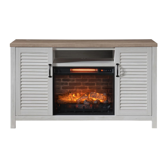
- Page 1 54IN. TWO TONE SHUTTER DOOR FIREPLACE CONSOLE ASSEMBLY INSTRUCTION ITEM# C2820 SKU# 810571321 Need help? We are here for you at biglots@aplusint.com...
-
Page 2: Maintenance
GENERAL BEST PRACTICES FOR ASSEMBLY Read all instructions before starting Clear a flat covered space to begin We recommend two adults for assembly Note that hardware required is provided for every step Pay attention to orientation Letter of the part corresponds to a sticker on the product Number of the hardware corresponds to its number in the package Helpful hints provided along the way WARNINGS... -
Page 3: Parts List
PARTS LIST PART DESCRIPTION QTY PART NO. PART DESCRIPTION QTY PART NO. Top Panel C2820-A Upper Back Board C2820-J Bottom Panel C2820-B Bottom Panel Rail C2820-K Left Side Panel C2820-C Bottom Support C2820-L Right Side Panel C2820-D Top Panel Rail... -
Page 4: Hardware List
HARDWARE LIST Shelf Pin (8x) Tip Restraint Hardware (1x) TOOL LIST Phillip #3 Screwdriver (1x) Page 4... -
Page 5: Safety Information
SAFETY INFORMATION IMPORTANT INSTRUCTIONS When using electrical appliances, basic precautions should always be followed to reduce the risk of fire, electric shock and injury to persons, including the following. DANGER To reduce the risk electrical shock, tipping and instability of the product. ·... -
Page 6: Electrical Connection
SAFETY INFORMATION (CONTINUED) CAUTION DO NOT operate any heater with a damaged cord or plug or after the heater malfunction. DO NOT operate any heater if it has been dropped or damaged in any manner. Disconnect power at service panel and have the heater inspected by a reputable electrician before reusing. ·... - Page 7 STEP 1 Attach the Bottom Support (L) to the Bottom Panel Rail (K) STEP 2 Clockwise Insert the assembled Bottom Panel Rail (K,L) into the holes on the Bottom Panel (B). Using the included Phillip #3 Screwdriver (CC), turn the Locking Nut in clockwise direction up to 180°...
- Page 8 STEP 3 Attached the two Side Panels (C,D) to the assembled Bottom Panel (B). Turn the Clockwise Locking Nut in clockwise direction up to 180° from the connection joint to properly secure the panels. Carefully turn the assembled parts upright. 180°...
- Page 9 STEP 5 Assemble the Middle Shelf (H) in between the two Center Panels (E,F). First, slot in the two dowels at the back of the Middle Shelf into the holes on the Center Panels. Then swing the Middle Shelf downwards until the Shelf Nut enters the Pins on the Center Panels.
- Page 10 STEP 7 Slide in the Back Boards (I) into the grooves on the Side Panels (C,D) and Center Panels (E,F). Push the Back Boards downwards until they are fitted into the Back Board Tightening Nuts on the Bottom Panel (B). Back Board STEP 8 Slide in the Upper Back Board (J) into the grooves on the Center Panels (E,F).
- Page 11 STEP 9 Clockwise Assemble the Top Panel (A) onto the Side Panels (C,D) and Center Panels (E,F). Turn the Locking Nut in clockwise direction up to 180°from the connection joint to properly secure the panels. 180° STEP 10 Insert the Top Pin of the Right Door (O) into the hole underneath the Top Panel (A).
- Page 12 STEP 9 Insert the Shelf Pins (AA) provided into the holes on the Side Panels (C,D) and Center Panels (E,F) at desired height, ensuring they are level. Place the Shelves (G) on top of the Shelf Pins. Shelf Pin (8x) TIP RESTRAINT HARDWARE Assembly is not complete.
- Page 13 FIREPLACE HEATER - PARTS LIST The Fireplace is Ready-To-Assemble. A Phillip #3 Screwdriver is the only tool required to assemble the heater. PART DESCRIPTION QTY PART NO. PART DESCRIPTION QTY PART NO. Bottom Panel AF02-1 Front Tempered Glass AF02-6 Left Side Panel AF02-2 Back Board AF02-7...
- Page 14 FIREPLACE HEATER - STEP 1 Attach the Side Panels (2,3) to the Bottom Panel (1). Turn the Locking Nut in Clockwise clockwise direction by 180° to secure the panels. 180° FIREPLACE HEATER - STEP 2 Slide in the Tempered Glass (6) into the grooves on the front of the Side Panels (2,3). Page 14...
- Page 15 FIREPLACE HEATER - STEP 3 Open the Side Panels (2,3) sideways a bit. Insert the Heater (8) in between the two Clockwise side panels by matching the pins and bolt on the heater to the holes on the Side Panels. Turn the Locking Nut in clockwise direction by 180° to secure the heater. 180°...
- Page 16 FIREPLACE HEATER - STEP 5 Slide in the Back Board (7) into the grooves on the Back Rails (4,5). Slide in until the Back Board is tightened by the Nut at the bottom. The Nut will ensure that the box is straightened and the Back Board is secured.
- Page 17 FINAL ASSEMBLY COMPLETED. The Console and the Heater is now assembled and you may now insert the Heater into the Console to complete the assembly. (See Page 18) Page 17...
- Page 18 INSERTION OF HEATER INTO ASSEMBLED CABINET Once the Fireplace Heater (P) is fully assembled, it can be easily inserted into a TV Stand. The Heater is inserted into a TV Stand simply by sliding it from the front of the TV Stand. ·...
- Page 19 REMOVAL OF HEATER FROM ASSEMBLED CABINET To remove the Fireplace, the following are the steps. · Raise the Middle Shelf (H) a bit. Then tilt the Fireplace towards the front so that the Spring Guide is out of the hole. ·...
-
Page 20: Control And Display
OPERATING INSTRUCTIONS Control Panel Remote Control To use the remote control, first remove the plastic tab by gently pulling it out of the remote control CONTROL AND DISPLAY The control panel will display the heater setting when the unit power is turned ON. Whichever control icon you press will display the current setting of the corresponding function. - Page 21 OPERATING INSTRUCTIONS (CONTINUED) HEATER FUNCTION · Press the HEATER ICON to display the current heater setting. · Press the HEATER ICON again to cycle through the heater settings. · Set the heater to "HI" (High) to have the heater run continuously. ·...
-
Page 22: One-Year Limited Warranty
ONE-YEAR LIMITED WARRANTY The manufacturer warrants that your new Electric Fireplace is free from manufacturing and material defects for a period of one year from date of purchase, subject to the following conditions and limitations. Install and operate this Electric Fireplace in accordance with the installation and operating instructions furnished with the product at all times.
Need help?
Do you have a question about the C2820 and is the answer not in the manual?
Questions and answers