Allied Telesis TQ6403 GEN2 Installation Manual
Hide thumbs
Also See for TQ6403 GEN2:
- Installation manual (68 pages) ,
- Quick installation manual (4 pages)

Related Manuals for Allied Telesis TQ6403 GEN2


Summary of Contents for Allied Telesis TQ6403 GEN2
- Page 1 Draft 4 on July 20, 2022 TQ6403 GEN2 IEEE802.11ax tri-radio 5G/5G/2.4GHz 2x2+2x2+2x2+BLE wireless AP TQm6403 GEN2 IEEE802.11ax tri-radio 5G/5G/2.4GHz 2x2+2x2+2x2 wireless AP Installation Guide 613-003092 Rev. A...
- Page 2 Allied Telesis, Inc. has been advised of, known, or should have known, the...
- Page 3 Draft 4 on July 20, 2022 TQ6403 GEN2 and TQm6403 GEN2 Access Points Installation Guide Electrical Safety and Emissions Standards This product meets the following standards: “Federal Communications Commission Interference Statement” “European Union Restriction of the Use of Certain Hazardous Substances (RoHS) in Electrical ...
- Page 4 Radiation Exposure Statement: This equipment complies with FCC radiation exposure limits set forth for an uncontrolled environment. The TQ6403 GEN2 and TQm6403 GEN2 access points should be installed and operated with minimum distance 51 cm between the radiator and your body.
- Page 5 Draft 4 on July 20, 2022 TQ6403 GEN2 and TQm6403 GEN2 Access Points Installation Guide Safety and Electromagnetic Emissions Standard Compliance RoHs compliant European Union RoHS (Directive 2011/65/EU of the European Parliament and of the Council of 8 June 2011 on the restriction of the use of certain hazardous substances in electrical and electronic equipment.)
- Page 6 Draft 4 on July 20, 2022 Electro Magnetic Interference (EMI) FCC part15 Subpart B/ Class B EN55032 Class B VCCI-CISPR 32 / Class B AS/NZS CISPR 32 Electro Magnetic Susceptibility - EN55024 and EN55035 IEC 61000-4-2 ...
- Page 7 Draft 4 on July 20, 2022 TQ6403 GEN2 and TQm6403 GEN2 Access Points Installation Guide AS/NZS CISPR 32 AS/NZS 4268 ICES-003 RSS-102 RSS-247 Japan JATE ARIB STD-T66 ARIB STD-T71 Hong Kong OFCA...
- Page 8 PDF document titled Translated Safety Statements on the Allied Telesis website at www.alliedtelesis.com/library. Remarque: Les consignes de sécurité portant le symbole sont traduites dans plusieurs langues dans le document Translated Safety Statements, disponible à...
-
Page 9: Table Of Contents
Draft 4 on July 20, 2022 Contents Preface ................................15 Safety Symbols Used in this Document ....................16 Contacting Allied Telesis ........................... 17 Chapter 1: Product Description ........................19 Features ..............................20 Hardware Components ..........................21 Cable Hide............................23 Console Port............................23 Power Switch............................ - Page 10 Draft 4 on July 20, 2022 Contents PoE+ Power Requirements........................56 Cable Specifications ...........................57 LAN Ports Specifications and Pinouts ......................58 Port Specifications ..........................58 Port Pinouts............................58 Appendix B: Regulatory Statements ......................59 Federal Communication Commission Interference Statement ..............60 Industry Canada Statement........................62 Europe - EU Declaration of Conformity ......................64 Operating Frequencies and Maximum Transmission Power Levels ............64 Radiation Exposure Statement ......................64...
- Page 11 Draft 4 on July 20, 2022 Figures Figure 1: Singapore IMDA Logo ........................7 Figure 2: Access Point Top View........................21 Figure 3: Access Point Bottom View ....................... 21 Figure 4: Front Edge View..........................22 Figure 5: Back Edge View ..........................22 Figure 6: Left Edge View ..........................
- Page 12 Draft 4 on July 20, 2022 List of Figures...
- Page 13 Draft 4 on July 20, 2022 Tables Table 1. LED Status Information ........................29 Table 2. Physical Specifications ........................55 Table 3. Environmental Specifications ......................55 Table 4. External AC/DC Adapter Specifications ................... 56 Table 5. PoE+ Power Specifications on LAN Ports ..................56 Table 6.
- Page 14 Draft 4 on July 20, 2022 List of Tables...
-
Page 15: Preface
This guide contains the hardware installation instructions for the following access points: TQ6403 GEN2 TQm6403 GEN2 This preface contains the following sections: “Safety Symbols Used in this Document” on page 16 “Contacting Allied Telesis” on page 17 ... -
Page 16: Safety Symbols Used In This Document
Draft 4 on July 20, 2022 Preface Safety Symbols Used in this Document This document uses the following conventions. Note Notes provide additional information. Caution Cautions inform you that performing or omitting a specific action may result in equipment damage or loss of data. Warning Warnings inform you that performing or omitting a specific action may result in bodily injury. -
Page 17: Contacting Allied Telesis
user guides, software release notes, white papers and data sheets for your product. Warranty - View a list of products to see if Allied Telesis warranty applies to the product you purchased and register your warranty. Allied Telesis Helpdesk - Contact a support representative. - Page 18 Draft 4 on July 20, 2022 Preface...
-
Page 19: Chapter 1: Product Description
Draft 4 on July 20, 2022 Chapter 1 Product Description The sections in this chapter describe the hardware components of the TQ6403 GEN2 and TQm6403 GEN2 access points: “Features” on page 20 “Hardware Components” on page 21 “LAN1 and LAN2 Ports” on page 24 ... -
Page 20: Features
Band steering Wi-Fi multimedia (WMM) for prioritizing traffic Wi-Fi 6 BLE/IEEE 802.15.4 (TQ6403 GEN2 only) Features of Power and Power over Ethernet (PoE): PoE+ (IEEE 802.3at) Power saving mode: support IEEE802.3af when either one or two ... -
Page 21: Hardware Components
Draft 4 on July 20, 2022 TQ6403 GEN2 and TQm6403 GEN2 Access Points Installation Guide Hardware Components The top view of the TQ6403 GEN2 and TQm6403 GEN2 access points is illustrated in Figure 1. Back Edge Front Edge Figure 1. Access Point Top View The bottom view is illustrated in Figure 2. - Page 22 Draft 4 on July 20, 2022 Chapter 1: Product Description The front edge view is illustrated in Figure 3. Mounting Bracket Thumb Screw Hole Figure 3. Front Edge View The back edge view is illustrated in Figure 4. Console Port DC IN Connector for AC/DC Adapter LAN1 POE+ Port Power Switch...
-
Page 23: Cable Hide
Draft 4 on July 20, 2022 TQ6403 GEN2 and TQm6403 GEN2 Access Points Installation Guide Cable Hide The top cover of the access point is larger than the access point chassis to create space on the back for cable connectors and cables shown in Figure 2 on page 21. -
Page 24: Lan1 And Lan2 Ports
Draft 4 on July 20, 2022 Chapter 1: Product Description LAN1 and LAN2 Ports The wireless access point has two Ethernet ports, labeled LAN1 and LAN2. You use the ports to connect the wireless access point to your wired network. Here are their basic properties: LAN1 and LAN2 ports support PoE+. -
Page 25: Cascade Mode
Draft 4 on July 20, 2022 TQ6403 GEN2 and TQm6403 GEN2 Access Points Installation Guide Note Do not enable and cable the LAN2 port until after you have configured the other network device for the static LAG. Cascade Mode The LAN2 port also has a Cascade mode. The mode allows you to use the port to connect another device to your network. -
Page 26: Power Over Ethernet Plus (Poe+)
Draft 4 on July 20, 2022 Chapter 1: Product Description Power Over You can power the wireless access point with either PoE+ on the LAN1 port, LAN2 port or an AC/DC power adapter. The wireless access point is Ethernet Plus a PoE+ Class 4 powered devices, with maximum power consumption of (PoE+) 25.5 watts. -
Page 27: Cable Requirements
Draft 4 on July 20, 2022 TQ6403 GEN2 and TQm6403 GEN2 Access Points Installation Guide You cannot disable automatic MDIX detection. For automatic MDIX detection to work properly, this feature must also be present on the Ethernet switch. The LAN port defaults to MDIX if it is connected to a network device that does not support automatic MDIX detection. -
Page 28: Ac Adapter For External Power Supply
AC power adapter as its primary power source and PoE+ as redundant power. For technical specifications, refer to “Power Specifications” on page 56. The PWRADP-01 (DA-48Z12) Power Adapter, shown in Figure 9, from Allied Telesis is approved for this product. Figure 9. PWRADP-01 (DA-48Z12) Power Adapter... -
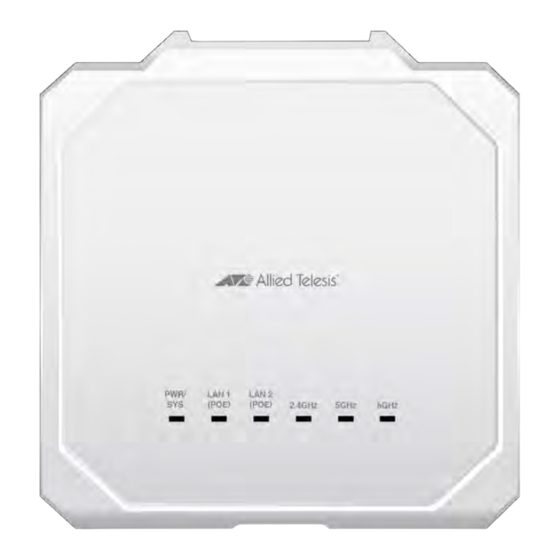
Page 29: Leds
Draft 4 on July 20, 2022 TQ6403 GEN2 and TQm6403 GEN2 Access Points Installation Guide LEDs The LEDs on the top panel display status information. See Figure 10 for LEDs and Table 1 for the status definition. Figure 10. Top View - LEDs Table 1. - Page 30 Draft 4 on July 20, 2022 Chapter 1: Product Description Table 1. LED Status Information (Continued) State Description Green The 2.4GHz radio is enabled. 2.4GHz The 2.4GHz radio is disabled. Green The 5GHz radio is enabled. 5GHz-1 The 5GHz radio is disabled. Green The 5GHz radio is enabled.
-
Page 31: Chapter 2: Installing The Wireless Access Point
Draft 4 on July 20, 2022 Chapter 2 Installing the Wireless Access Point This chapter contains the installation procedures for the TQ6403 Access Points. The procedures are detailed in the following sections: “Reviewing Safety Precautions” on page 32 “Unpacking the Shipping Box” on page 35 ... -
Page 32: Reviewing Safety Precautions
Draft 4 on July 20, 2022 Chapter 2: Installing the Wireless Access Point Reviewing Safety Precautions Please review the following safety precautions before installing the access point. Important: Safety statements that have the symbol are translated into multiple languages in the Translated Safety Statements document, which is available at www.alliedtelesis.com/library. - Page 33 Draft 4 on July 20, 2022 TQ6403 GEN2 and TQm6403 GEN2 Access Points Installation Guide Warning FCC Caution: Any changes or modifications not expressly approved by the party responsible for compliance could void the user's authority to operate this equipment.
- Page 34 Draft 4 on July 20, 2022 Chapter 2: Installing the Wireless Access Point Note If you are not using PoE to power to unit, use only an approved AC/ DC adapter. Refer to “Power Specifications” on page 56. Caution The unit does not contain serviceable components. Please return damaged units for servicing.
-
Page 35: Unpacking The Shipping Box
Draft 4 on July 20, 2022 TQ6403 GEN2 and TQm6403 GEN2 Access Points Installation Guide Unpacking the Shipping Box To verify the contents of the shipping box, perform the following procedure: 1. Remove all components from the shipping box. Note Store the packaging material in a safe location. -
Page 36: Reviewing Installation Guidelines
Draft 4 on July 20, 2022 Chapter 2: Installing the Wireless Access Point Reviewing Installation Guidelines Review the following guidelines before installing the access point: The ceiling or wall mounting surface must be of proper material to accommodate the screws and strong enough to support the weight of the access point and cables. - Page 37 Draft 4 on July 20, 2022 TQ6403 GEN2 and TQm6403 GEN2 Access Points Installation Guide Ceiling Installation Wall Installation Table Installation Figure 12. Approved Installation Orientations on a Ceiling, Wall, or Table...
-
Page 38: Installing The Access Point On A Table
Chapter 2: Installing the Wireless Access Point Installing the Access Point on a Table You need the following items to install the access point on a table: TQ6403 GEN2 or TQm6403 GEN2 Access Point One or two Ethernet cables ... -
Page 39: Overview To Installing The Access Point On A Wall Or Ceiling
Draft 4 on July 20, 2022 TQ6403 GEN2 and TQm6403 GEN2 Access Points Installation Guide Overview to Installing the Access Point on a Wall or Ceiling Here are the procedures for installing the wireless access point on a wall or ceiling: “Pre-fitting the Mounting Bracket on the Access Point”... -
Page 40: Pre-Fitting The Mounting Bracket On The Access Point
Draft 4 on July 20, 2022 Chapter 2: Installing the Wireless Access Point Pre-fitting the Mounting Bracket on the Access Point To pre-fit the mounting bracket on the access point, perform the following procedure: 1. Place the wireless access point upside down on a table. 2. - Page 41 Draft 4 on July 20, 2022 TQ6403 GEN2 and TQm6403 GEN2 Access Points Installation Guide 3. Make sure that the mounting bracket fits to the access point by sliding the bracket beneath the screws as shown in Figure 15. Figure 15. Attaching the Mounting Bracket on the Access Point 4.
-
Page 42: Installing The Mounting Bracket On A Wall Or Ceiling
Draft 4 on July 20, 2022 Chapter 2: Installing the Wireless Access Point Installing the Mounting Bracket on a Wall or Ceiling To install the mounting bracket on a wall of ceiling, perform the following procedure: 1. Choose the location and orientation for the access point on the wall or ceiling. - Page 43 Draft 4 on July 20, 2022 TQ6403 GEN2 and TQm6403 GEN2 Access Points Installation Guide 5. Install two M4 screws and anchors (if required). Leave the screws loose enough so that the bracket can slide under the screw heads. Refer to Figure 18.
- Page 44 Draft 4 on July 20, 2022 Chapter 2: Installing the Wireless Access Point 6. Insert the openings of the bracket key-hole slots under the two screw heads and slide the bracket into the narrow end of the key-hole slot openings. See Figure 19. Figure 19.
- Page 45 Draft 4 on July 20, 2022 TQ6403 GEN2 and TQm6403 GEN2 Access Points Installation Guide 9. Install and tighten two M4 screws (not provided) in the holes prepared in Step 8. The bracket installation is now complete.See Figure 21. Figure 21. Securing the Mount Bracket 10.
-
Page 46: Connecting Ethernet Cables To Lan1 And Lan2 Ports
Draft 4 on July 20, 2022 Chapter 2: Installing the Wireless Access Point Connecting Ethernet Cables to LAN1 and LAN2 Ports This section describes the instructions for connecting Ethernet cables to the LAN1 and LAN2 ports. Guidelines Review the following guidelines before connecting cables to the LAN1 and LAN2 ports: For information on cable specifications, see “Cable Requirements”... - Page 47 Draft 4 on July 20, 2022 TQ6403 GEN2 and TQm6403 GEN2 Access Points Installation Guide 2. Connect the other end of the Ethernet cable to a network Ethernet device, such as an Ethernet switch or router. Note If the device is PoE+ power sourcing equipment (PSE), the access point begins to power on and initialize its management software.
-
Page 48: Connecting The Ac Power Adapter
AC power adapter, or both. A wireless access point that is powered by both methods uses the AC adapter as its primary power and PoE as redundant power. For an AC power adapter, Allied Telesis recommends the MWS0091 Power Adapter. -
Page 49: Attaching The Access Point To The Mounting Bracket
Draft 4 on July 20, 2022 TQ6403 GEN2 and TQm6403 GEN2 Access Points Installation Guide Attaching the Access Point to the Mounting Bracket To attach the wireless access point on the mounting bracket on the wall or ceiling, perform the following procedure: 1. - Page 50 Draft 4 on July 20, 2022 Chapter 2: Installing the Wireless Access Point Figure 26. Seating the Access Point on the Mounting Bracket 3. Tighten the thumbscrew to secure the access point to the mounting bracket. Refer to Figure 27. Figure 27.
- Page 51 Draft 4 on July 20, 2022 TQ6403 GEN2 and TQm6403 GEN2 Access Points Installation Guide 4. Place the Ethernet cable(s) and power cable (if any) along the cable guides inside of the top cover in the cable hide space. See Figure 28.
-
Page 52: Installing An Anti-Theft Device
Note Anti-theft devices are not available from Allied Telesis. 1. Follow the instructions provided with the vendor’s anti-theft device for the installation. See Figure 29 for the Kensington lock port location. -
Page 53: Starting The First Management Session
Draft 4 on July 20, 2022 TQ6403 GEN2 and TQm6403 GEN2 Access Points Installation Guide Starting the First Management Session This section contains an abbreviated version of the procedure to start the first management session. For complete instructions, refer to the TQ6403 GEN2 and TQm6403 GEN2 Management Software User’s Guide. - Page 54 Draft 4 on July 20, 2022 Chapter 2: Installing the Wireless Access Point...
-
Page 55: Appendix A: Technical Specifications
Draft 4 on July 20, 2022 Appendix A Technical Specifications This appendix contains the specifications for the TQ6403 Access Points in the following sections: “Physical Specifications” “Environmental Specifications” “Power Specifications” on page 56 “Cable Specifications” on page 57 ... -
Page 56: Power Specifications
Table 5 lists the PoE+ specifications for the PoE LAN ports. Requirements Table 5. PoE+ Power Specifications on LAN Ports TQ6403 GEN2 TQm6403 GEN2 Maximum Power Consumption 24.1 watts 23.9 watts Rated Voltage DC 48V Rated Current 0.67A Note Allied Telesis recommends using UL-certified PoE injectors. -
Page 57: Cable Specifications
Draft 4 on July 20, 2022 TQ6403 GEN2 and TQm6403 GEN2 Access Points Installation Guide Cable Specifications The minimum cable requirements for ports LAN1 and LAN2 are listed here. 100Mbps ports: Standard TIA/EIA 568-B-compliant Category 3 shielded or unshielded cabling. -
Page 58: Lan Ports Specifications And Pinouts
Draft 4 on July 20, 2022 Appendix A: Technical Specifications LAN Ports Specifications and Pinouts Port The access point port specifications are shown in Table 6. Specifications Table 6. LAN Port Specifications Connector Specification PoE standard - LAN1 and LAN2 IEEE 802.3at (class 4) Port Pinouts The pin signal definitions for ports LAN1 and LAN2 are given here. -
Page 59: Appendix B: Regulatory Statements
Draft 4 on July 20, 2022 Appendix B Regulatory Statements This appendix contains the following regulatory statements: “Federal Communication Commission Interference Statement” on page 60 “Industry Canada Statement” on page 62 “Europe - EU Declaration of Conformity” on page 64 ... -
Page 60: Federal Communication Commission Interference Statement
Draft 4 on July 20, 2022 Appendix B: Regulatory Statements Federal Communication Commission Interference Statement This device complies with Part 15 of the FCC Rules. Operation is subject to the following two conditions: (1) This device may not cause harmful interference, and (2) this device must accept any interference received, including interference that may cause undesired operation. - Page 61 Draft 4 on July 20, 2022 TQ6403 GEN2 and TQm6403 GEN2 Access Points Installation Guide Radiation Exposure Statement This equipment complies with FCC radiation exposure limits set forth for an uncontrolled environment. The TQ6403 GEN2 and TQm6403 GEN2 access points should be installed and operated with minimum distance 51...
-
Page 62: Industry Canada Statement
Draft 4 on July 20, 2022 Appendix B: Regulatory Statements Industry Canada Statement This device contains licence-exempt transmitter(s)/receiver(s) that comply with Innovation, Science and Economic Development Canada’s licence- exempt RSS(s). Operation is subject to the following two conditions: (1) This device may not cause interference. (2) This device must accept any interference, including interference that may cause undesired operation of the device. - Page 63 Cet équipement est conforme aux limites d'exposition aux rayonnements ISED établies pour un environnement non contrôlé. Les points d'accès TQ6403 GEN2 et TQm6403 GEN2 doivent être installés et utilisés avec une distance minimale de 25 cm entre le radiateur et votre corps.
-
Page 64: Europe - Eu Declaration Of Conformity
Appendix B: Regulatory Statements Europe - EU Declaration of Conformity Hereby, Allied Telesis declares that the radio equipment type [TQ6403 GEN2, TQm6403 GEN2] is in compliance with Directive 2014/ 53/EU. Operating The operating frequencies and maximum transmission power levels for... -
Page 65: Uk - Ukca Declaration Of Conformity
TQ6403 GEN2 and TQm6403 GEN2 Access Points Installation Guide UK - UKCA Declaration of Conformity Hereby, Allied Telesis declares that the radio equipment type [TQ6403 GEN2, TQm6403 GEN2] is in compliance with the Radio Equipment Regulations 2017 Operating The operating frequencies and maximum transmission power levels for... - Page 66 Draft 4 on July 20, 2022 Appendix B: Regulatory Statements...
Need help?
Do you have a question about the TQ6403 GEN2 and is the answer not in the manual?
Questions and answers