Zennio Z41 Pro Technical Documentation
Capacitive color touch panel with ip connection
Hide thumbs
Also See for Z41 Pro:
- User manual (169 pages) ,
- How to configure (15 pages) ,
- Technical documentation (2 pages)
Advertisement
Table of Contents
- 1 Features
- 2 General Specifications
- 3 Internal Temperature Sensor and Clock Specifications
- 4 External Power Supply and Ports Specifications and Connections
- 5 Inputs Specifications and Connections
- 6 Installation Instructions
- 7 General Care
- 8 Safety Instructions and Additional Notes
- Download this manual
Capacitive color touch panel with IP connection
ZVI-Z41PRO
FEATURES
•
4.1'' capacitive color touch panel (320x240 pixels)
•
Available in the following colors: silver (Pantone 10105C), anthracite black
(Pantone Black U), white (NCS 500-N) and gloss white (Pantone RB82798)
•
16 million color LCD display
•
Up to 12 configurable pages
•
Up to 96 configurable direct control and/or indicator functions
•
2 independent thermostats
•
2 analog/digital inputs
•
Customized device orientation (Vertical or Horizontal)
•
Built-in temperature sensor
•
Real Time Clock (RTC) with watch battery and NTP support
•
External 12-29 VDC power supply
•
Integrated KNX BCU (TP1-256)
•
Mini-USB and Ethernet connection
•
Magnetic fit
•
Complete data saving in case of power failure
•
Conformity with the CE, UKCA, RCM directives (marks on the back side)
1. Temperature probe
6. Programming LED
Programming button: short press to set programming mode. If this button is held while plugging the device into the KNX bus, it enters the safe mode.
Programming LED: programming mode indicator (red). When the device enters the safe mode, it blinks (red) every half second. During the start-up
(reset or after KNX bus failure) and if the device is not in safe mode, it emits a red flash.
GENERAL SPECIFICATIONS
CONCEPT
Type of device
Voltage (typical)
Voltage range
KNX supply
Maximum
consumption
Connection type
External power supply
Operation temperature
Storage temperature
Operation humidity
Storage humidity
Complementary characteristics
Protection class
Operation type
Device action type
Electrical stress period
Degree of protection
Installation
Minimum clearances
Response on KNX bus failure
Response on KNX bus restart
Response on power supply failure
Response on power supply recovery
Operation indicator
Accessories
Weight
PCB CTI index
Housing material
¹ Maximum consumption in the worst-case scenario (KNX Fan-In model).
© Zennio Avance y Tecnología S.L.
2. KNX connector
3. Input connector
7. Ethernet connector
Voltage
29 VDC (typical)
24 VDC¹
Edition 11
4. Battery
8. Magnet
9. Mini-USB connector
DESCRIPTION
Electric operation control device
29 VDC SELV
21-31 VDC
mA
6
10
Typical TP1 bus connector for 0.8 mm Ø rigid cable
12-29 VDC. Maximum consumption: 250 mA (12 VDC), 112 mA (24 VDC),
86 mA (29 VDC). Do not connect 29 VDC KNX bus as external power
supply
5 .. +45 °C
-20 .. +55 °C
5 .. 95%
5 .. 95%
Class B
III
Continuous operation
Type 1
Long
IP20, clean environment
Portrait or landscape position, with the temperature sensor at the bottom or
right, respectively. Magnetic fit. See Installation instructions section.
Please, keep away from heat and cold air flows to get better temperature
measurements.
Data saving according to parameterization. Initialization screen.
Data recovery according to parameterization
Complete data saving. Display is switched off
Current data recovery
Several on display as programmed
RJ45 cable connector (included). Mini USB A-B cable Ref. ZN1AC-UPUSB
(not included)
237 g (Al) / 226 g (PC)
175 V
PC+ABS FR V0 halogen free
Further information
TECHNICAL DOCUMENTATION
Ref. ZN1-HOLDER
(included)
9
10
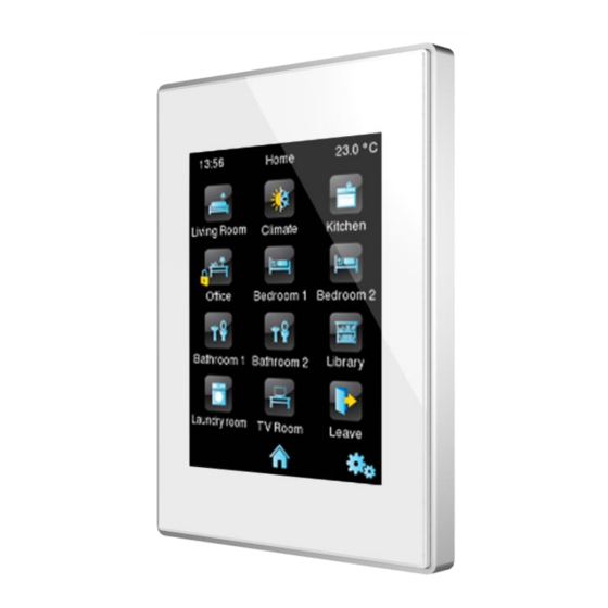
Figure 1: Z41 Pro
5.Programming button
10. External power supply connector
mW
174
240
www.zennio.com
Z41 Pro
7
8
6
5
4
3
2
1
Page 1/2
Advertisement
Table of Contents

Related Manuals for Zennio Z41 Pro


Summary of Contents for Zennio Z41 Pro
- Page 1 237 g (Al) / 226 g (PC) PCB CTI index 175 V Housing material PC+ABS FR V0 halogen free ¹ Maximum consumption in the worst-case scenario (KNX Fan-In model). © Zennio Avance y Tecnología S.L. Edition 11 Further information www.zennio.com Page 1/2...
- Page 2 Once it is connected, fit Z41 Pro in the metal platform. The device is fixed through the magnets. Slid Z41 Pro downwards to fix it with the security anchorage system. Check, from the side, that nothing unless Z41 Pro outline can be seen (the metal platform should be completely hidden by Z41 Pro).
Need help?
Do you have a question about the Z41 Pro and is the answer not in the manual?
Questions and answers