
Related Manuals for Zennio Z70 v2


Summary of Contents for Zennio Z70 v2
- Page 1 Z70 v2 KNX Full Color Capacitive Touch Panel with 7” display ZVIZ70V2 Application Program Version: [3.0] User Manual Version: [3.0]_b www.zennio.com...
-
Page 2: Table Of Contents
Z70 v2 CONTENTS Contents ............................2 Document updates ........................4 Introduction .......................... 5 Z70 v2 ..........................5 Functionality ........................7 Installation ........................9 Start-up........................10 1.4.1 EULA ........................... 10 Configuration........................11 General ........................11 2.1.1 Configuration ......................11 2.1.2 Locale ......................... 16 2.1.3 Backlight ........................ - Page 3 Z70 v2 ANNEX I. Video Intercom Operation ................... 98 Incoming Call ........................... 98 Ongoing Call ..........................99 Previewing images from the camera ..................100 Call Log ..........................101 ANNEX II. Internal Call Operation ....................103 Outcoming Call ........................103 Incoming Call ......................... 105 Ongoing Call ..........................
-
Page 4: Document Updates
Z70 v2 DOCUMENT UPDATES Version Changes Page(s) Changes in the document: • Reference to the specific document “Firmware [3.0]_b Update” is included. Changes in the application program: [3.0]_a • Date/time synchronisation via NTP • Remote control of the device http://www.zennio.com Tecnical Support: http://support.zennio.com... -
Page 5: Introduction
1.1 Z70 V2 Z70 v2 is the easily and intuitively controllable high-performance colour touch screen from Zennio. The built-in features and functions make it the ideal solution for integral room control in hotels, offices or any other environments where controlling climate systems, lighting systems, shutters, scenes, etc. - Page 6 4 customisable analogue-digital inputs. Heartbeat or periodic “still-alive” notification. Elegant design, available in various colours. Z70 v2 also has additional functionalities that require the use of a license in order to operate: Video Intercom compatible with GetFace IP. Internal Calls between different Z70 v2 (also compatible with Z41 COM).
-
Page 7: Functionality
Z70 v2 1.2 FUNCTIONALITY Z70 v2 application program feature the following functions: 12 General-Purpose Pages, with up to 12 Fully-Customisable Boxes each, which the integrator may configure as indicators or controls. ➢ Indicators: o Binary. o Float. o Enumeration. o Temperature. - Page 8 Z70 v2 1 Configuration Page (optional), which contains the time/date settings, the calibration of the built-in temperature probe, and the brightness and doorbell volume and tone adjustment, among others. http://www.zennio.com Tecnical Support: http://support.zennio.com...
-
Page 9: Installation
Temperature probe. Figure 1 Schematic diagram. Z70 v2 is connected to the KNX bus through the built-in terminal (7). An external DC power supply (24V / 29V) which delivers at least 200 mA of current is also required. The KNX power and the external power must be provided by separate supplies, in order to avoid interference to the KNX bus. -
Page 10: Start-Up
1.4 START-UP 1.4.1 EULA After the first start-up of the device, Z70 v2 will display a dialog with the text EULA (End User License Agreement). The legal conditions of use described in EULA must be accepted by the end user before using the screen, so during the installation must be postponed. -
Page 11: Configuration
Z70 v2 2 CONFIGURATION After importing the corresponding database in ETS and adding the device into the topology of the desired project, the configuration process begins by entering the Parameters tab of the device. 2.1 GENERAL This tab is divided into multiple screens, all of which contain a set of global parameters regarding the general functionality of the device, and therefore not specifically related to a particular page of the user interface. - Page 12 Z70 v2 The following parameters are shown: : enables or disables the “Inputs” tab in the tree on the left, Inputs [disabled/enabled] depending on whether the device will or will not be connected any external accessories. For more information, see section 2.3.
- Page 13 Z70 v2 Synchronize Clock Master via NTP [disabled/enabled]: if enabled, the device will update the date and time obtained from the NTP server according to the configured time zone. In addition, the following parameters will be displayed: ➢ Time Zone: drop-down list to select a time zone from the UTC (Coordinated Universal Time) time standard.
- Page 14 Please refer to the user manual “Proximity and Luminosity Sensor” (available in the Z70 v2 product section at the Zennio homepage, www.zennio.com) for detailed information about the functionality and the configuration of the related parameters. Note: After programming or resetting the device, 1 minute is required to carry out the sensors calibration.
- Page 15 Z70 v2 calculates it from the date and therefore ignores that field. Important: Z70 v2 does not have an RTC clock or battery to keep track of the time in the absence of power. Therefore, it is important to receive the time periodically from a device that obtains it through NTP and/or has a battery to prevent delays during bus failures.
-
Page 16: Locale
[General] Localization – Select: 4-byte object to change the locale in the screen (see section 2.1.2). [General] Translations – Select: 2-byte object to change the language in the Z70 v2 (see section 2.1.2). [Profile] Theme: 1-byte object to change the theme used in the screen. - Page 17 Z70 v2 Use of a point (.) or a comma (,) for decimal separation (except in temperature that will always be shown with a point as separator). Position of the currency symbol in cost indicators. Language of all the texts shown on the screen.
- Page 18 Z70 v2 ETS PARAMETERISATION Figure 7. Locale Main Locale [enabled]: read-only parameter to make it evident that the main locale is always enabled. ➢ Select Locale: list of the available locales. Locale X [disabled/enabled]: enables the additional locale X. ➢ Select Locale: list of the available locales.
- Page 19 Z70 v2 the main locale configuration will be loaded. If the region does not correspond to the language or it is not valid, the default region associated with that language will be set (and the language file 'text_language-ZZ.xlf', if it exists).
-
Page 20: Backlight
Note: Contrast is not a configurable feature in the device. Please refer to the specific manual “Brightness” (available in the Z70 v2 product section at the Zennio website, www.zennio.com) for detailed information about the functionality and the configuration of the related parameters. - Page 21 Z70 v2 In case of setting up two levels, the first one is assumed to be enclosed by the second one. This means that whenever the device asks the user to type password #1 (to enter a certain item); password #2 will also be accepted. On the contrary, password #1 cannot be used instead of password #2.
- Page 22 Z70 v2 twice, being the first one referred to the password of Level 1, and the second one to the password of Level 2. Figure 10. Two security levels Important: the password insertion dialog features a specific option (lower left button) that lets the user change, in runtime, the passwords originally set by parameter.
-
Page 23: Internal Temperture Sensor
2.1.6 AMBIENT LUMINOSITY SENSOR Z70 v2 includes a sensor to measure the ambient luminosity level, so that the brightness of the display can be adjusted according to the current luminosity of the room. Please refer to the specific manual “Luminosity and Proximity Sensor” (available in the Z70 v2 product section at the Zennio homepage, www.zennio.com) for detailed information about... -
Page 24: Sounds
Locked]: textbox to enter the desired message. 2.1.8 SOUNDS Z70 v2 emits 3 types of sounds, depending on the action performed: Press Confirmation: short beep indicating that the user has pressed a button. This only applies to step controls, i.e., controls that go through a certain range of values and that do not send a value after every touch, and to page accesses. - Page 25 Z70 v2 Enabling and disabling of this function can only be done by parameter. If enabled, the volume of the press and sending confirmation sounds will be possible to define. ETS PARAMETERISATION After enabling the “Custom” configuration of Sounds from “Configuration” screen (see section ¡Error! No se encuentra el origen de la referencia.), a new tab will be incorporated into the...
-
Page 26: Update Setting
USB port (see 8 in Figure 1), through the proper adapter cable. When the Z70 v2 recognizes the inserted USB flash memory, a USB icon will appear on the top bar and an informational message will appear on the screen. The actions notified will be: http://www.zennio.com... - Page 27 2.1.9.2 LICENCE SETUP Some of the functionalities available in Z70 v2 require the installation of a license for their use. If it is not pre-installed, it will be provided by Zennio in a .lic file.
- Page 28 Export: it must be created an empty folder named “lang_export” on the root directory of a pen drive and connect it to the Z70 v2. When the Z70 v2 detects the inserted USB flash drive, a USB icon appears in the top bar and an information dialog appears on the screen.
- Page 29 To do this, it is necessary to follow the nomenclature “text_language- ZZ.xlf”. Once the translations are finished, plug in the USB to the Z70 v2 and, when the Z70 v2 detects the inserted USB flash drive, a USB icon appears in the top bar and an information dialog appears: ➢...
- Page 30 Z70 v2 directory of the USB, which in turn will have a certain folder structure depending on whether or not different icon sets for each theme wants to be differentiated: Without differentiating theme: in this case the imported icons will be common for both light and dark theme.
- Page 31 Z70 v2 After completing the above steps and connecting the USB to the Z70 v2, as soon as the Z70 v2 identifies the inserted USB flash drive, a USB icon will appear in the top bar and a dialog will inform the user of the action on screen: “New icons imported”.
-
Page 32: Ip Configuration
Z70 v2 2.1.10 IP CONFIGURATION Z70 v2 is able to communicate with other external (GetFace IP) or internal (Z70 v2 or Z41 COM) units via Ethernet connection. Such communications will require correct configuration of certain general IP parameters. ETS PARAMETERISATION Figure 18. -
Page 33: Voip Calls (License Required)
A Zennio outdoor unit: GetFace IP. These calls are referred in this document as video intercom calls. The same GetFace IP outdoor unit can call more than one Z70 v2 at the same time. For that purpose, the different Z70 v2 must be synchronized and connected to the same network. - Page 34 “[VoIP] “Do Not Disturb” Mode”: 1-bit object that enables and disables the do not disturb mode of the Z70 v2 VoIP functionality. While this mode is active, Z70 v2 will not receive any incoming calls, but the calls will be recorded in the log.
- Page 35 Video Intercom. For further information see section 2.2.2.1.5.5. Up to 20 outdoor units are available in a Z70 v2, each one controlling up to 4 doors, for a total of up to 84 doors controllable by one Z70 v2. GetFace IP is responsible for controlling the doors locks.
- Page 36 Name: text field identifying the parameterised outdoor unit. This name will be displayed both in the Z70 v2 call log and on the top bar of incoming and ongoing calls. / Community]: The “Private” type enables access at any time to the...
- Page 37 Note: the characters included in this field must comply RFC 2396 standard. Set Static IP [disabled / enabled]. If Z70 v2 and GetFace IP are in different networks, IP Address [192.168.1.201] of GetFace IP must be set, in addition to Specifying Gateway, in “IP Configuration” tab (see section 0).
- Page 38 Door n [disabled/enabled]: enables or disables every door, up to 4 for each outdoor unit. Note: the door concept in Z70 v2 refers to the switches configured in GetFace IP in section Hardware Switches.
- Page 39 ETS, its use will not be accessible. Z70 v2 can, via its Ethernet connection, make and receive calls from others Z70 v2 and Z41 COM that will be registered. The access to the internal call history will be enabled as long as, at least one box is configured as an internal call (see section 2.2.2.1.5.6).
- Page 40 Z70 v2 To receive calls, each of the screens involved in the communication must have the other configured as a contact. In a Z70 v2 up to 8 contacts can enable and configure or be imported up to 100 via web.
- Page 41 ETS will enable to configure a list of up to 8 contacts for each Z70 v2. For Z70 v2 to be able to make calls to other screens (Z70 v2 or Z41 COM), certain data, such as the ID and IP address of each contact, will need to be correctly configured. Otherwise, communication between devices will not take place.
-
Page 42: Avanced
Z70 v2 Name [Contact n]: name that will be displayed both in the call log and in the contact list. ID [IC_n]: Contact identifier. IP Address [192.168.1.111]: IP address of the contact. Important: both the IP address and ID must match the IP Address and My ID set in the "IP Settings"... - Page 43 Z70 v2 2.1.12.1 CLEANING FUNCTION This feature is very similar to the touch locking, that is, it locks the touch area, thus discarding further button touches. The difference is that this function remains active only during a parameterisable time, and then stops.
- Page 44 Z70 v2 Time to Exit Cleaning Status [5...15…65535][s] [1…65535][min/h]: timeout to deactivate the cleaning function after triggered. Message Notification [Cleaning…]: textbox to enter the desired message. Notify Expiration / Blink Message / Play Sound / Both]: sets whether to notify the timeout expiration or not.
- Page 45 Z70 v2 ETS PARAMETERISATION After enabling Pop-Ups from “Advanced” screen (see section 2.1.12), a new tab will be incorporated into the tree on the left. Figure 29. Pop-ups tab Pop-Up n [disabled/enabled]: allows to enable/disable each pop-up. After enabling each pop-up, a new tab will be incorporated into the tree on the left named “Pop-Up n”.
- Page 46 “Text Received from Object”. 2.1.12.3 WELCOME BACK OBJECT Z70 v2 can send a specific object to the KNX bus when the user presses a touch button after a significant amount of time since the last press or presence detection (when the proximity sensor is enabled).
- Page 47 Z70 v2 ETS PARAMETERISATION After enabling Welcome Back Object from “Advanced” screen (see section 2.1.12), a new tab will be incorporated into the tree on the left. Figure 31. Welcome Back Object. Time to Activate the Welcome Object [30...65535][s] [1…65535][min/h] : sets the...
- Page 48 Z70 v2 Welcome Back Object (Scene) [disabled/enabled]: checkbox to enable the sending of a scene run request (through “[General] Scene: send”) when the welcome back function is triggered and the condition (if any) evaluates to true. The desired value should to be set in Scene Number [1…64].
-
Page 49: Display
Z70 v2 2.2 DISPLAY 2.2.1 PAGES The user interface is organised into pages (up to twelve different pages, in addition to the ‘Configuration Page’), each of which can be accessed from the Menu page, which (unless the contrary has been parameterised) is automatically shown after the start-up. - Page 50 Z70 v2 ETS PARAMETERISATION Figure 34. General pages configuration The parameters available are: Number of Pages [1…12]: number of general purpose pages that will be activated on the device. For each page a dedicated ETS tab will be shown for configuration.
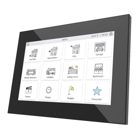
- Page 51 Z70 v2 2.2.1.1 MENU The user interface may have up to twelve pages of general purpose, each of which can host up to twelve different controls or indicators. Figure 35. Menu Page ETS PARAMETERISATION The Menu tab allows defining generic options regarding the enabled control pages, which can be accessed from this screen.
- Page 52 Z70 v2 ➢ Use this Text in the Device [disabled/enabled]: allows the text to be used as the page title in the device. Automatic Page Shaping / Yes]: allows choosing whether the pages in Menu should be automatically distributed (“Yes”) depending on the number of pages configured, or be displayed as a static 3x4 grid (“No”).
- Page 53 Z70 v2 Figure 38. Configuration tab Title: text field that identifies the configuration page. In addition, this field allows changing the name of the tab in ETS left menu, as shown in the Figure 38. ➢ Use this Text in the Device [disabled/enabled]: allows the text to be used as the page title in the device.
- Page 54 Z70 v2 • / Level 1 / Level 2]: sets the level of security to access the configuration page. Time/Date [disabled/enabled]: if enabled, the date and time of the device can be set directly from the user interface: Figure 39. Time and date.
- Page 55 Z70 v2 This centralised file may be useful when the user needs to check the status of a set of alarm controls distributed across several pages. Figure 40. Alarm Log To delete the record, press and hold the button , at the bottom right of the window for more than 3 seconds.
- Page 56 Z70 v2 2.2.1.2.1 Device Z70 v2 configuration page, if Device is enabled, will display a button allowing access to several controls and indicators with device-specific information: Figure 41. Device. ETS PARAMETERISATION After enabling the Device from “Configuration Page” screen (see section 2.2.1.2), a new tab will be incorporated into the tree on the left.
- Page 57 Moreover, for all these controls, the following parameter can be configured: Label: text that will appear to identify the box. 2.2.1.2.2 Profile Z70 v2 configuration page, if Device is enabled, will display a button to access the visual and sound settings of the device: Figure 43. Profile http://www.zennio.com...
- Page 58 Note: Doorbell boxes will be only available if the “Object for Doorbell” parameter is enabled in the custom sounds tab (see section 2.1.8). 2.2.1.2.3 VoIP Calls (License Required) Z70 v2 configuration page, if VoIP Calls is enabled, will display a button to access the video intercom and internal call settings of the device: http://www.zennio.com Tecnical Support: http://support.zennio.com...
- Page 59 Z70 v2 Figure 45. VoIP Calls ETS PARAMETERISATION After enabling the VoIP Calls from “Configuration Page” screen (see section 2.2.1.2), a new tab will be incorporated into the tree on the left. Figure 46. Configuration page - VoIP calls Video Intercom Ringtone [disabled/enabled]: box to change the melody to be played when receiving a call from an external unit.
- Page 60 2.2.1.3 PAGE N Z70 v2 has up to twelve general purpose pages that can be enabled from the "Pages" tab. Thus, a new tab called Page n will be displayed for each of the n enabled pages. Inside each page, the desired controls can be placed as boxes arranged in order, according to the parameters for each page.
- Page 61 Z70 v2 Figure 48. 2x2 Box Visualization ETS PARAMETERISATION Figure 49. Configuration Page n This screen contains the following parameters: Title: text field that identifies each of the enabled pages. In addition, this field allows changing the name of the tab in ETS left menu, as shown in the Figure 49.
-
Page 62: Controls
Z70 v2 Note: a list with all icons available can be found in document “Z70 v2 Icon list”, available at www.zennio.com. / Control 1…Control 144]: allows selecting which control, Control Distribution [Nothing from a list of 144 controls, will be placed in each of the twelve possible boxes on the screen. - Page 63 ➢ Use this Text in the Device [disabled/enabled]: allows the text to be used as the box label where this control is placed in the device. Visualization: box format. The available box formats in Z70 v2 are: http://www.zennio.com Tecnical Support:...
- Page 64 At the end of the list, the custom icons (“Cx”) that must have been previously imported in Z70 v2, can be selected (see section 2.1.9.4). Note: a list with all icons available can be found in document “Z70 v2 Icon list”, available at www.zennio.com.
- Page 65 Z70 v2 2.2.2.1.1.1 Binary When this function is assigned to a control, the “[Ci] Binary Indicator” communication object become available, as well as following parameters: Figure 53. Indicator - Binary. Indicator Type [Icon / Text]: allows selecting whether the status represented by each indicator value will be text type or icon type.
- Page 66 Z70 v2 Indicator Type [Icon / Text]: allows selecting whether the status indicator which each value is represented will be text type or icon type. As many drop-down lists of icons or text boxes will be displayed as states have been enabled in the previous parameter.
- Page 67 Z70 v2 ➢ The temperature indicator will be shown in ºC or ºF depending on the active locale (see section 2.1.2). In addition, the following parameters will be available for this control type: • Button to Change between ºC and ºF [disabled/enabled]: enables a control that allows the temperature scale to be changed from the box itself: Figure 56.
- Page 68 Z70 v2 Figure 58. 1-Button Control - Switch Action [Send 0 / Send 1 / Toggle 0/1]: specifies what value will be sent to the bus after pressing the control button. Indicator Type [Icon / Text]: allows selecting whether the status represented by each indicator value will be text type or icon type.
- Page 69 Z70 v2 Different objects are used to send values for short and long pulsations: "[Ci] Two objects - Short Press" and "[Ci] Two objects - Long Press", respectively. If the option chosen is “Send 0” or “Send 1”, the object "[Ci] Two objects - Indicator"...
- Page 70 Z70 v2 Figure 61. 1-Button Control - Scene Action [Run / Run and Save]: sets whether the device will only send scene execution orders (after a short press) or if it will be possible, to send scene save orders (after a long press).
- Page 71 Z70 v2 shows the permitted value range and the name of the object through which the values are sent to the bus. Function Size Sign Range Related Object Unsigned [0…255] [Ci] 1-Byte Unsigned Int Control 1 Byte Signed [-128…0…127] [Ci] 1-Byte Signed Int Control...
- Page 72 Z70 v2 / Pop-Up 1 / … / Pop-Up 6]: allows to select Show Pop-Up When Activating MUR the pop-up to be displayed when the MUR mode is activated. Note: the pop-ups selected must be activated (see section 2.1.12.2). This control will have associated a dedicated object for the indicator (“[Ci] Room State Indicator”), which is automatically updated after the control order is sent and when values are...
- Page 73 Z70 v2 2.2.2.1.3 2-BUTTON CONTROL The box configured with this control type will have a button at the right and a state indicator. In addition, through Function parameter, it will be possible to select the specific function that the control will perform.
- Page 74 In the same way the previous control, when pressing in any of the controls configured as switch, Z70 v2 will send the parameterized binary value to the bus through the object "[Ci] Switch". However, the indicator is independent and will only be updated according to the value received by the dedicated object.
- Page 75 Z70 v2 ➢ For percentage indicator, the symbol % always will be displayed as unit. ➢ The temperature indicator will be shown in ºC or ºF depending on the value of the active locale (see section 2.1.2). In addition, the following parameters will be available for this control type: •...
- Page 76 Z70 v2 Long Press Threshold Time [4…6…50] [ds]: sets the minimum time the user should hold the button in order to consider it a long press. State Object [Short Press Object / Long Press Object]: allows setting the control command to which the status indicator, "[Ci] Two Objects - Indicator", will obey. This object can also receive values from the bus.
- Page 77 Z70 v2 Increment on Increment on Related Object Function Size Sign Minimum Value Maximum Value short press long press [Ci] 1-Byte Signed Int Indicator Signed [-128…127] [-128…127] [1…127] [1…10…127] [Ci] 1-Byte Signed Int Control 1 Byte [Ci] 1-Byte Unsigned Int Indicator Unsigned [0…255]...
- Page 78 Z70 v2 Indicator Type [Icon / Text]: allows selecting whether the status indicator which each value is represented will be text type or icon type. As many drop-down lists of icons or text boxes will be displayed as states have been enabled in the previous parameter.
- Page 79 Z70 v2 2.2.2.1.3.7 Shutter Shutter control permits sending move up and move down ("[Ci] Shutter - Move”) or stop (“[Ci] Shutter – Stop/Step”) to control a shutter actuator connected to the bus by pressing the buttons in the box. In addition, the box will contain an indicator that will permanently show, as a percentage, the value of the status object (“[Ci] Shutter Position”).
- Page 80 25%, but a progressive increment or decrement of the light level by 25% which is in fact interrupted if a stop order arrives (such order is sent by Z70 v2 when the user releases the button). Due to this behaviour, it is advised to parameterise dimming steps of 100%, so that the user can perform a complete dimming (from totally off to totally on, or vice http://www.zennio.com...
- Page 81 Z70 v2 versa) or a partial dimming by simply holding the button and then releasing it as soon as he gets the desired light level, therefore with no need of performing successive long presses for regulations greater than the parameterised step.
- Page 82 Z70 v2 2.2.2.1.4 CLIMATE CONTROL This category covers a set of functions related to the climate control. The available options for Function (and for the dependent parameters) are as follows: 2.2.2.1.4.1 Temperature Setpoint This function permits controlling the temperature setpoint of an external thermostat by means of a two-button box and of the parameters enabled to that effect: “[Ci] (Climate) Setpoint...
- Page 83 Z70 v2 Button to Change between ºC and ºF [disabled/enabled]: enables a control that allows the temperature scale to be changed from the box itself: Include Plus Sign before Positive Numbers [disabled/enabled]: adds the ‘+’ sign before positive temperature values.
- Page 84 Z70 v2 2.2.2.1.4.2 Mode This function turns the box into a climate mode control. When this type of mode control is assigned to the box, two communication objects are enabled: the “[Ci] (Climate) Mode Control” control object, and the “[Ci] (Climate) Mode Indicator”...
- Page 85 Z70 v2 which of all the five extended modes will be included into the sequential scrolling implemented by the buttons. Figure 79 Climate Control - Extended Mode ➢ Depending on the mode selected by the user, the control object will be sent to the bus a certain value (see Table 7.
- Page 86 Z70 v2 When this function is assigned to the box, a control object and a 1-byte status object (“[Ci] (Climate) Fan Indicator”) are enabled. The status object (which needs to be linked to the status object of the fan actuator) will express, as a percentage, the value of the current fan level, which will be represented with a variable icon on the box.
- Page 87 Z70 v2 Figure 81 Fan Control – Auto Mode. In case to be disabled (supposing that Speed Levels has been set to “3”), the fan levels that can be navigated through short presses are: Auto ( 0 ) Minimum Medium...
- Page 88 Z70 v2 ( 0 ) Minimum Medium Maximum Here, the Auto mode is only activated by long press. Allow speed 0: sets whether the speed level 0 will be present or not. When the Auto Mode without a dedicated object has been configured, this option will be necessarily activated.
- Page 89 Z70 v2 Special Mode Icon Object Value Comfort 1 (0x001) Standby 2 (0x002) Economy 3 (0x003) Protection 4 (0x004) Auto Mode 5 (0x005) Table 8. Special Modes vs. Icon vs. Object Value Indicator Type [Icon / Text]: allows selecting whether the status indicator which each value is represented will be text type or icon type.
- Page 90 Z70 v2 ➢ “Three Single Colour Objects (DPT 5.001)”: three 1-byte objects (“[Ci] Red Channel”, “[Ci] Green Channel” and “[Ci] Blue Channel”) will be enabled, which can send orders and receive statuses. ➢ “One RGB Object (DPT 232.600)”: only one 3-byte object will be enabled (“[Ci] RGB Color”).
- Page 91 Z70 v2 2.2.2.1.5.2 RGBW Control The RGBW control is analogous to the above RGB control, although it also lets controlling a specific fourth channel for white (“[Pn][Bi] White Channel”). It also has the particulary of being able to choose a colour object.
- Page 92 In addition, the screen will automatically browse to the page containing the alarm box that has been triggered and pop-ups that were open will be deactivated. Note: if the Z70 v2 is locked, the lock pop-up will not be closed, but the alarms will be silenced with a press on the screen.
- Page 93 Trigger [0 / 1]: defines the value that will trigger the alarm (“0” or “1”; it is “1” by default), i.e., the value that, when received through “[Ci] Alarm Trigger”, should be interpreted by Z70 v2 as an alarm situation. Implicitly, this parameter also defines the inverse “no alarm” value.
- Page 94 [Generic preview window is opened. For more detailed information about the functions and controls of the different dialogues that appear in Z70 v2 in relation to video intercom functionalities, please refer to ANNEX I. Video Intercom Operation. http://www.zennio.com Tecnical Support:...
- Page 95 Z70 v2 2.2.2.1.5.6 Internal Call Note: Internal Call functionality requires a license installation. If not, even being possible to configure it from ETS, its use will not be accessible. This control enables access to the contacts list or number keypad in order to start a call (top button) and to the internal calls log (bottom button): Figure 93.
- Page 96 Figure 96. Numeric Keypad. For more detailed information about the functions and controls of the different dialogues that appear in Z70 v2 in relation to internal calls functionalities, please refer to ANNEX II. Internal Call Operation. http://www.zennio.com Tecnical Support: http://support.zennio.com...
-
Page 97: Inputs
Temperature Probe, to connect a temperature from Zennio. Motion Detector, to connect a motion detector from Zennio. 2.3.1 BINARY INPUT Please refer to the specific user manual “Binary Inputs”, available in the Z70 v2 product section, at the Zennio website (www.zennio.com). 2.3.2 TEMPERATURE PROBE Please refer to the specific user manual “Temperature Probe”, available in the Z70 v2 product... -
Page 98: Annex I. Video Intercom Operation
Z70 v2 ANNEX I. VIDEO INTERCOM OPERATION INCOMING CALL When Z70 v2 receives a call from a video door phone, the user interface in Figure 97 will be displayed. Figure 97. Incoming call During an incoming call, besides displaying the camera image, the following functions will be... -
Page 99: Ongoing Call
Mute Call: mutes the call ringtone in Z70 v2 and the rest of the synchronized screens will be notified. ONGOING CALL When accepting the incoming call, Z70 v2 shows the interface in Figure 100 and starts the voice communication with the GetFace IP. Figure 100. Ongoing call During an ongoing call the functions available are: Hang up Call: ends the communication and closes the ongoing call dialog. -
Page 100: Previewing Images From The Camera
2.1.11.1.1 and 2.1.11.1.2, a communication object. Note: if outdoor unit IP is not specified in the Z70 v2 settings, the preview of the camera image and the door opening will not be accessible until at least one incoming call has been received. -
Page 101: Call Log
A box configured as a Video Intercom (see section 2.2.2.1.5.5) has a button to access to a Call Log. Every call that Z70 v2, or the other synchronized devices, receives will be registered as a new entry in the call history. The information shown in each entry is as follows: Figure 102. - Page 102 Z70 v2 The video intercom name from which the call was made. First image captured at the start of the call. Note: if the video intercom does not have a camera or has not been possible to save the image, the image area will be empty.
-
Page 103: Annex Ii. Internal Call Operation
The communication with the selected contact will be carried out after clicking on the accept call button. The Z70 v2 that is making the call will show the interface of Figure 105, in which the following elements will be available: Figure 105. - Page 104 Z70 v2 Reject call: rejects the call, causing the other Z70 v2 to display a message that the call has ended: Figure 106. Message – Internal call ended. Note: Call will be cancelled if there is no answer within one minute.
-
Page 105: Incoming Call
The labels of the previously mentioned messages are editable (see section 2.1.11.2). INCOMING CALL When Z70 v2 is receiving a call from another screen, the following dialogue will be showed: Figure 109. Incoming call The following items are available during an incoming internal call: Name assigned to the contact from whom the call is received. -
Page 106: Ongoing Call
If a box is configured as internal calls (see section 2.2.2.1.5.6), a button will be available to access a call log. Every internal call that Z70 v2 receives or makes will be recorded as a new entry in the call history. The information shown in each entry is as follows: http://www.zennio.com... - Page 107 Z70 v2 Figure 111. Internal call log Date and time of the call. Whether the call has been attended , considering attended calls the accepted and the rejected calls, not attended or outgoing . Moreover, if there is a not attended call since the last time the call log was accessed, the indicative icon appears the internal call box and on the page where the box is located.
-
Page 108: Annex Iii. Remote Control Via Ip
Z70 V2 CONFIGURATION In order to be able to control Z70 v2 from remote applications it is necessary that the integrator enables in ETS the parameter Remote control through the Internet inside the " Configuration"... - Page 109 Z70 v2 Note: Pairing multiple Z70 v2 to a particular remote application is possible, as well as pairing a particular Z70 v2 to multiple remote applications. PAIRING PROCEDURE Once Z70 v2 has been configured as described, pressing on the Device Pairing box will bring up a pop-up window similar to Figure 114.
- Page 110 Note: Zennio Avance y Tecnología S.L. does not accept any responsibility for losses of “push” messages due to network, hardware or software failures of any kind.
-
Page 111: Annex Iv. Communication Objects
Z70 v2 ANNEX IV. COMMUNICATION OBJECTS “Functional range” shows the values that, with independence of any other values permitted by the bus according to the object size, may be of any use or have a particular meaning because of the specifications or restrictions from both the KNX standard or the application program itself. - Page 112 Z70 v2 1 Byte C - W T - DPT_Scaling 0% - 100% [Profile] Volume 0% … 100% 1 Bit C - W - - DPT_Ack [General] Doorbell 1 = Play Doorbell 1 Bit C - W - - DPT_Ack...
- Page 113 Z70 v2 163, 164, 170, 171, 172, 173, 179, 180, 181, 182, 188, 189, 190, 191, 197, 198, 199, 200, 206, 207, 208, 209, 215, 216, 1 Bit C - W - - DPT_Ack [VI x] Trigger Switch x 0 = Open...
- Page 114 Z70 v2 671, 675, 679, 683, 687, 691, 1 Byte C - W T U DPT_Scaling 0% - 100% [Cx] Percentage Indicator 0% … 100% 695, 699, 703, 707, 711, 715, 2 Bytes C - W T U 9.xxx -671088.64 - 670433.28 [Cx] 2-Byte Float Indicator -671088.64 ...
- Page 115 Z70 v2 480, 484, 488, 492, 496, 500, [Cx] Two Objects - Short 1 Bit C R - T - DPT_Switch 1-Bit Generic Control 504, 508, 512, 516, 520, 524, Press: “0” 528, 532, 536, 540, 544, 548, [Cx] Two Objects - Short...
- Page 116 Z70 v2 [Cx] (Climate) Fan Control 1 Byte C R - T - DPT_Scaling 0% - 100% 100% (Scaling) [Cx] (Climate) Fan Control 1 Byte C R - T - DPT_Scaling 0% - 100% 50%, 100% (Scaling) [Cx] (Climate) Fan Control...
- Page 117 Z70 v2 [Cx] (Climate) Fan Control 1 Byte C R - T - DPT_Fan_Stage 0 - 255 0, 1, 2, 3 (Enumeration) [Cx] (Climate) Fan Control 1 Byte C R - T - DPT_Fan_Stage 0 - 255 0, 1, 2, 3, 4...
- Page 118 Z70 v2 732, 734, 736, 738, 740, 742, 744, 746, 748, 750, 752, 754, 756, 758, 760, 762, 764, 766, 768, 770, 772, 774, 776, 778, 780, 782, 784, 786, 788, 790, 792, 794, 796, 798, 800, 802, 804, 806, 808, 810, 812, 814,...
- Page 119 Z70 v2 505, 509, 513, 517, 521, 525, [Cx] Two Objects - Long Press: 1 Bit C R - T - DPT_Switch 1-Bit Generic Control 529, 533, 537, 541, 545, 549, “0/1” 553, 557, 561, 565, 569, 573, [Cx] Two Objects - Long Press:...
- Page 120 Z70 v2 0 = Night Mode; 1 = Normal 1 Bit C - W - - DPT_DayNight [General] Backlight Mode Mode 0 = Normal Mode; 1 = Night 1 Bit C - W - - DPT_DayNight [General] Backlight Mode Mode...
- Page 121 Z70 v2 0x7 (Dec. by 1%) 0x8 (Stop) 0xD (Inc. by 100%) 0xF (Inc. by 1%) 0x0 (Stop) 0x1 (Dec. by 100%) 0x7 (Dec. by 1%) [Ix] [Short Press] 4 Bit C - - T - DPT_Control_Dimming Switch Bright/Dark 0x8 (Stop) Brighter/Darker 0xD (Inc.
- Page 122 Z70 v2 [Ix] [Long Press] Stop/Step Switching of 0/1 (Stop/Step 1 Bit C - - T - DPT_Step Shutter (Switched) Up/Down) 0x0 (Stop) 0x1 (Dec. by 100%) 0x7 (Dec. by 1%) Long Pr. -> Brighter; Release -> 4 Bit C - - T -...
- Page 123 Z70 v2 [Ix] [Long Press] Shutter 1 Byte C - W - - DPT_Scaling 0% - 100% 0% = Top; 100% = Bottom Status (Input) 1017 1 Byte C - W - - DPT_SceneNumber 0 - 63 [Motion Detector] Scene Input Scene Value...
- Page 124 Z70 v2 1037, 1042, 1047, 1066, 1071, 1076, 1095, 1100, 1 Bit C - W - - DPT_Switch [Ix] [Cx] Force State 0 = No Detection; 1 = Detection 1105, 1124, 1129, 1134 [Internal Temp. Probe] Current 1135 2 Bytes...
- Page 125 Z70 v2 1 Bit C - W - - DPT_Reset [Tx] Setpoint Reset Reset Setpoint to Default 1172, 1210 1 Bit C - W - - DPT_Reset [Tx] Offset Reset Reset Offset 1173, 1211 1 Bit C - W - -...
- Page 126 Join and send us your inquiries about Zennio devices: http://support.zennio.com Zennio Avance y Tecnología S.L. C/ Río Jarama, 132. Nave P-8.11 45007 Toledo (Spain). Tel. +34 925 232 002. www.zennio.com info@zennio.com...
Need help?
Do you have a question about the Z70 v2 and is the answer not in the manual?
Questions and answers