
Related Manuals for Hioki 3227


Summary of Contents for Hioki 3227
- Page 1 INSTRUCTION MANUAL For...は専用機種。複数の場合は「/」で区切る。不要の場合はとる。 形名を入力。 複数の場合は「/」で区切る。 3227 品名を入力。 mΩ HiTESTER...
-
Page 3: Table Of Contents
Contents Introduction Inspection Safety Notes Notes on Use Organization of this Manual Chapter 1 Overview 1.1 Features 1.2 Specifications 1.2.1 General Specifications 1.2.2 Resistance Measurement 1.2.3 Temperature Measurements 1.2.4 Temperature Correction Function 1.3 Measurements and Working Systems 1.3.1 4-terminal Measurements 1.3.2 Temperature Probe 1.3.3 Measurement Value Display 1.3.4 Comparator Function... - Page 4 Chapter 4 Basic Operations 4.1 Operating Procedure 4.1.1 Function Classes 4.1.2 Key Shift States 4.1.3 Key Lock State 4.1.4 Remote State 4.1.5 Valid Input Key Table 4.2 Selecting the Measurement Mode 4.3 Resistance Measurement Mode 4.3.1 Selecting the Sampling Rate 4.3.2 Selecting the Measuring Range 4.3.3 Zero Adjustment 4.4 Resistance Measurement...
- Page 5 8.3.12 Event Register 8.3.13 GP-IB Commands 8.4 Command Reference 8.5 Command Summary 8.5.1 Standard Command 8.5.2 Commands Specific to the 3227 8.6 Valid Command According to the Modes 8.7 Initialization 8.8 Notes on GP-IB Interface 8.9 Sample Programs 8.9.1 Hewlett Packard Series 300 Sample Programs...
- Page 6 Chapter 9 Printer Interface 9.1 Printer Interface 9.1.1 Connecter 9.1.2 Connecting Method 9.2 Print Method Chapter 10 Maintenance and Service 10.1 Changing the Fuse 10.1.1 Power Fuse 10.1.2 Circuit Protection Fuse 10.2 Disposing the Unit 10.3 Trouble Shooting...
-
Page 7: Introduction
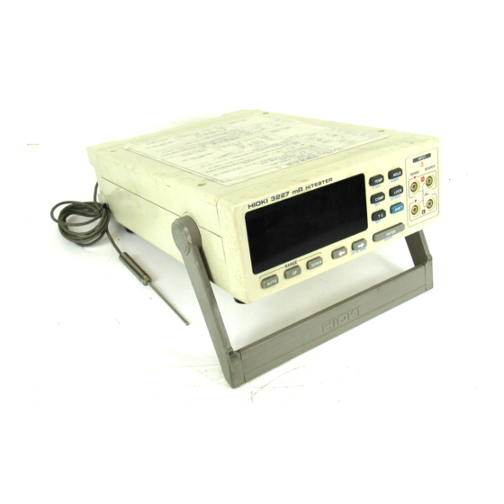
──────────────────────────────────────────────────── Introduction Thank you for purchasing this HIOKI "3227 mΩ HiTESTER." To get the maximum performance from the unit, please read this manual first, and keep this at hand. Inspection When the unit is delivered, check and make sure that it has not been damaged in transit. -
Page 8: Safety Notes
──────────────────────────────────────────────────── Safety Notes This Instruction Manual provides information and warnings essential for operating this equipment in a safe manner and for maintaining it in safe operating condition. Before using this equipment, be sure to carefully read the following safety notes. This equipment is designed to according to IEC 348 Safety Standards, WARNING and has been tested for safety prior to shipment. - Page 9 ──────────────────────────────────────────────────── The following symbols are used in this Instruction Manual to indicate the relative importance of cautions and warnings. Indicates that incorrect operation presents significant danger of WARNING accident resulting in death or serious injury to the user. Indicates that incorrect operation presents possibility of injury to the CAUTION user or damage to the equipment.
-
Page 10: Notes On Use
80% RH or less. Do not use the unit in direct sunlight, dusty conditions, or in the presence of corrosive gases. ・Do not measure the voltage applied point. Particularly, the 3227 would be damaged by induced voltage when measuring soon after the temperature rise test or the pressure test of the trans or the motor. - Page 11 ──────────────────────────────────────────────────── ・ Always set the power supply frequency before measurement. When it has NOTE been set incorrectly, inaccurate measurement would be performed. How to set this, Section 3.3, "Selecting the Power Supply Frequency." ・ Accurate measurement may be impossible in locations subject to strong external magnetic fields, such as transformers and high-current conductors, or in locations subject to strong external electric fields, such as radio transmission equipment.
-
Page 12: Organization Of This Manual
──────────────────────────────────────────────────── Organization of this Manual Chapter 1 Overview Summary and features of the 3227 Chapter 2 Part Names Description of part names Chapter 3 Unit Installation Preparation for measurements Chapter 4 Basic Operations Description of basic operations Chapter 5 Applied Operations... -
Page 13: Chapter 1 Overview
──────────────────────────────────────────────────── Chapter 1 Overview 1.1 Features (1) 10μΩ minimum high accuracy and high resolution resistance measurement, by 4-terminal measurement (2) High speed resistance measurement of 90 times/second in its top (3) Connecting the temperature probe makes 0℃ to 40℃ temperature measurement possible (4) Auto range function is contained (5) Measurement ranges can be selected from external control terminal. -
Page 14: Specifications
──────────────────────────────────────────────────── 1.2 Specifications 1.2.1 General Specifications Measurement method and 4-terminal and dual integrator circuit operating method Maximum number of display digit "30000" digit (3 digit when at FAST) Resistance measurement Temperature measurement "4000" digit "±999.9" 4 digit Temperature conversion Sampling rate "SLOW"... - Page 15 ──────────────────────────────────────────────────── Dielectric strength 1.5 kVAC Between the case and the input terminal Between the case and the power 1.5 kVAC (sensitivity current: 5 mA) supply line Insulation resistance Between the case and the input terminal (for a minute) Between the case and the power supply line (for a minute) 100 MΩ...
-
Page 16: Resistance Measurement
──────────────────────────────────────────────────── 1.2.2 Resistance Measurement 23℃±5℃ (73 F ±9 F), 80% RH or less (no condensation), Condition After zero adjustment 30 minutes Pre-heating period Accuracy assurance period 6 months Table 1 4-1/2 digit (sampling rate:SLOW) 3 Ω 30 Ω 300 Ω Range 300 mΩ... -
Page 17: Temperature Measurements
0.01℃ Resolution Accuracy ±0.5℃ Temperature coefficient ±0.02×(t-23)℃ t : environment temperature where the 3227 is located (℃). 1.2.4 Temperature Correction Function 0.00℃ to 40.00℃ (32 F to 104 F) Temperature correction range Standard temperature range -10.0℃ to 99.9℃ (14 F to 212 F) -
Page 18: Measurements And Working Systems
──────────────────────────────────────────────────── 1.3 Measurements and Working Systems 1.3.1 4-terminal Measurements Regular 2-terminal measurement measures even the value which includes the resistance of the measurement leads or the terminal area. Particularly, when measuring the low resistance, it is necessary to measure the value without this resistance value. -
Page 19: Temperature Probe
The temperature probe uses the platinum film resistor which is changeable according to the temperature, as the temperature sensor. This probe displays the resistance value of that register, detected by the 3227, after converting it to the temperature using the CPU. - Page 20 ℃ : αt = R × {1+α × (t−t The 3227 obtains the correctional resistance value (R ) from calculating the temperature measured by the temperature probe (t), the resistance value of the measured subjects (R ), the standard temperature (t ) and temperature coefficient (α...
- Page 21 If the temperature probe is to be used in the measurement, make sure that the 3227 and the temperature probe are thoroughly warmed up before the measurement. The temperature probe and the device to be measured should be placed close together during the warm-up, so that both will be as close to the same temperature as possible during the measurement.
-
Page 22: Measurement Value Display
──────────────────────────────────────────────────── 1.3.3 Measurement Value Display (1) Measurement value display Resistance measurement mode Resistance value display Display the resistance value of 4 digit (MEDIUM, SLOW) and 3 digit (FAST) by the sampling rate. Digit Display Digit Display Deviation display Display the deviation (see the expression below), when comparing with comparison of the standard value/range. - Page 23 ──────────────────────────────────────────────────── Temperature conversion mode When the temperature conversion function is selected at power on, when the TC indication on the display is on continuously the converted temperature value is displayed. When it is blinking, the temperature difference (Δt) is displayed. AUTO (2) The other display When the measurement value exceeds the measuring range (30000 count), the...
-
Page 24: Comparator Function
──────────────────────────────────────────────────── 1.3.4 Comparator Function There are 15 comparator setting tables in the 3227, and the different contents are able to set to each table. See Section 5.1, "Setting the Comparator" and Section 5.2, "Executing the Comparator", for how to set and execute the comparator. See Chapter 6, "External Control Terminals", for the external control terminals. - Page 25 ──────────────────────────────────────────────────── ・ When comparing by the standard value/range, the measurement value is NOTE displayed as the deviation. ・ Always set the high limit value bigger than the low limit value. ・ Ignoring the measurement range, perform the comparison only by the measurement count value.
- Page 26 ──────────────────────────────────────────────────── (1) Properties of metal and alloy conductive materials Annealed copper Tin-plated annealed Hard drawn copper Diameter [mm] wire copper wire wire 0.10 to 0.26 0.98 0.93 (excluding 0.26) 0.26 to 0.50 0.993 0.94 0.96 (excluding 0.50) 0.50 to 2.00 1.00 0.96 0.96...
-
Page 27: Chapter 2 Part Names
──────────────────────────────────────────────────── Chapter 2 Part Names 2.1 Front Panel INPUT HOLD TEMP SAMP 0 ADJ SENSE SOURCE ▼ LOCK COMP 50/60Hz SHIFT ▼ ENTER AUTO DOWN GP-IB ADRS CLEAR Display AUTO key UP key DOWN key Cusor keys ENTER key TEMP key (Temperature measurement (zero adjustment) ) HOLD key (Sampling rate setting) COMP key (Comparator setting) LOCK key (Power supply frequency setting) -
Page 28: Rear Panel
──────────────────────────────────────────────────── 2.2 Rear Panel Power supply inlet POWER switch Digital I/O connector Temperature probe connector External control terminal block Option slot ──────────────────────────────────────────────────── 2.2 Rear Panel... -
Page 29: Displays
──────────────────────────────────────────────────── 2.3 Displays Remote state Key shift state Comparator result Measurement value Key lock state REMOTE LOCK SHIFT F M S Sampling rate AUTO Auto range HOLD Hold state HIGH Measurement unit Comparator COMP Temperature correction High limit value Standard value Setting value Range Resistance coefficient... -
Page 30: Accessory And Options
──────────────────────────────────────────────────── 2.4 Accessory and Options Accessory 9188 TEMPERATURE PROBE Sensor part HIOKI 9188 MADE IN JAPAN Cable Connector Options 9588 GP-IB INTERFACE GP-IB connector 9588 GP-IB INTERFACE GP-IB MADE IN JAPAN 9589 PRINTER INTERFACE Printer connector 9589 PRINTER INTERFACE MADE IN JAPAN ────────────────────────────────────────────────────... -
Page 31: Chapter 3 Unit Installation
──────────────────────────────────────────────────── Chapter 3 Unit Installation 3.1 Installing the Interfaces The following is the explanation for the installing method of the 9588 GP-IB INTERFACE and the 9589 PRINTER INTERFACE. To prevent electric shock, before adding or replacing the interface, WARNING check that the power for the unit is off and the power cord and connectors are disconnected. - Page 32 1. Take off the blank plate. (Please keep the screws.) 2. Insert the interface with holding the guide rail between the rail of the 3227. 3. Insert the interface tightly, be sure to tighten the screws which have been unscrewed in step 1.
-
Page 33: Turning On The Power Supply
──────────────────────────────────────────────────── 3.2 Turning on the Power Supply (1) Confirm whether the power supply voltage shown on the rear panel and that intended to use are same. (2) Confirm whether the POWER switch is OFF. (3) Connect the accessory power code to the power supply inlet. (4) Connect the power code to the 3-pole power outlet which has the protective grounding terminal. - Page 34 ──────────────────────────────────────────────────── Display the name of this unit, the version number and the power supply frequency settings. TC on the display indicates the function to be used, the temperature correction function or temperature conversion function. When TC on the display is blinking, the temperature conversion function is used.
-
Page 35: Selecting The Power Supply Frequency
──────────────────────────────────────────────────── 3.3 Selecting the Power Supply Frequency 1. Press the key and enter the shift states. SHIFT SHIFT "SHIFT" on the display lights. 2. Press the key (power supply frequency setting LOCK LOCK key) and enter the power supply frequency setting 50/60Hz mode. -
Page 36: Preparation For Measurements
Insert the lead to the input terminal of the front panel. Connect them with putting the red ▼ mark of the 3227 upon the same mark of the red lead, and the black ▼ mark upon the same mark of the black lead. -
Page 37: Temperature Correction And Temperature Measurements
If the temperature probe is to be used in the measurement, make sure that the 3227 and the temperature probe are thoroughly warmed up before the measurement. The temperature probe and the device to be measured should be placed close together during the warm-up, so that both will be as close to the same temperature as possible during the measurement. -
Page 38: Handle Operation
──────────────────────────────────────────────────── 3.5 Handle Operation The handle is able to use as the stand. Pull the each side of the handle and turn it, then push it in. 。 The handle is able to fix every 22.5 . Use after fixing it to the proper direction. ────────────────────────────────────────────────────... -
Page 39: Chapter 4 Basic Operations
──────────────────────────────────────────────────── Chapter 4 Basic Operations 4.1 Operating Procedure 4.1.1 Function Classes Turning on the power Selecting the temperature correction/the temperature conversion Self test Resistance measurement mode Selecting the measurement range Selecting the sampling rate Comparator setting mode Selecting the comparator executing Temperature correction setting mode Selecting the temperature correction executing... -
Page 40: Key Shift States
In the each kind of setting mode, such as the comparator setting mode, when NOTE receiving any commands from GP-IB, the 3227 returns to the primary measurement mode automatically and enters the remote state. To release the remote state, press... -
Page 41: Valid Input Key Table
──────────────────────────────────────────────────── 4.1.5 Valid Input Key Table ● : Key input is valid. −: Key input is invalid. Out of the shift state In the shift state Lock Remote Keys Temper- Temper- state state Resistance Setting Resistance Setting ature ature TEMP ●... -
Page 42: Selecting The Measurement Mode
──────────────────────────────────────────────────── 4.2 Selecting the Measurement Mode Pressing the key (temperature measurement key) selects either the TEMP TEMP resistance measurement mode or the temperature measurement mode. 0 ADJ Resistance Measurement Mode Temperature Measurement Mode When the 9188 is not connected, the temperature mode is unable to select. If NOTE intend to select, error is generated. -
Page 43: Resistance Measurement Mode
──────────────────────────────────────────────────── 4.3 Resistance Measurement Mode 4.3.1 Selecting the Sampling Rate 1. Press the key and enter the shift states. "SHIFT" on the display SHIFT SHIFT lights. 2. Press the key (sampling rate setting key) and select the sampling SAMPL HOLD rate. -
Page 44: Selecting The Measuring Range
──────────────────────────────────────────────────── Temperature conversion display AUTO AUTO SLOW MEDIUM AUTO FAST When the sampling rate is FAST, 30 k and 300 kΩ range are unable to select. NOTE When set the sampling rate to FAST in 30 kΩ and 300 kΩ range, the measurement range becomes 3 kΩ... - Page 45 ──────────────────────────────────────────────────── The displays change as follows, according to the measuring range (in case of the resistance value display) 3 Ω range 300 mΩ range 30 Ω range 300 Ω range 3 kΩ range 30 kΩ range 300 kΩ range When intend to execute the comparator during using the auto range, the NOTE range becomes the manual range automatically.
-
Page 46: Zero Adjustment
──────────────────────────────────────────────────── 4.3.3 Zero Adjustment The zero adjustment cancels the wiring resistance in case that the accurate 4- terminal measurement is impossible. This is also able to execute from the external control terminal. See Chapter 6, "External Control Terminal", for details. (1) Short the leads as follows. -
Page 47: Resistance Measurement
──────────────────────────────────────────────────── 4.4 Resistance Measurement (1) Insert the measurement lead into the input terminal. See Section 3.4.1, "Resistance Measurement", for how to connect the measurement leads. To measure accurately, the leads should connect correctly. NOTE (2) Set the measurement mode to the resistance measurement. See Section 4.2, "Selecting the Measurement Mode", for how to select the measurement mode. -
Page 48: Temperature Measurement
・ If the temperature probe is to be used in the measurement, make sure that the 3227 and the temperature probe are thoroughly warmed up before the measurement. If it is not used to the surrounding temperature, the serious error is generated. -
Page 49: Holding The Measurement Value
──────────────────────────────────────────────────── 4.6 Holding the Measurement Value During holding the measurement, the value which is obtained on the HOLD key is pressed is held. The measurement and its display are not renewed except when the external control terminal requires the measurement. During free-running, they are renewed according to the rate which is set as the sampling rate. - Page 50 ──────────────────────────────────────────────────── ──────────────────────────────────────────────────── 4.6 Holding the Measurement Value...
-
Page 51: Chapter 5 Applied Operations
──────────────────────────────────────────────────── Chapter 5 Applied Operations 5.1 Setting the Comparator 5.1.1 Setting the Comparator 1 (1) Press the key and enter the shift states. "SHIFT" on the display lights. SHIFT SHIFT (2) Press the key and enter the comparator table setting mode. COMP COMP Comparator table number Buzzer mode... - Page 52 ──────────────────────────────────────────────────── While displaying the converted temperature, the 3227 has only one comparator setting table. In this case reference value/range comparisons also cannot be executed. The comparator setting in this case is displayed as shown below. HIGH (3)Move the flashing cursor to the setting items with the cursor keys.
-
Page 53: Setting The Comparator
──────────────────────────────────────────────────── 5.1.2 Setting the Comparator 2 (1)Pressing the cursor keys, enter the comparator setting mode. GP-IB ADRS Comparison HIGH method High limit value or standard value Low limit value or range In this mode, set the current comparator table to be used. When the NOTE comparator is not used, set the comparator table 1. -
Page 54: Eliminating The Comparator Table
──────────────────────────────────────────────────── 5.1.3 Eliminating the Comparator Table (1) Press the key and enter the shift states. SHIFT SHIFT "SHIFT" on the display lights. (2) Press the key and enter the comparator table COMP COMP setting mode. (3) Select the comparator table intend to eliminate. See Section 5.1.1, "Setting the Comparator Table", for details. -
Page 55: Executing The Comparator
──────────────────────────────────────────────────── 5.2 Executing the Comparator Pressing the key displays the comparator table number in order ("01" to COMP COMP "15", "OFF"). In this case, skip the comparator table which has not been set or been invalidated in Section 5.1.3, "Eliminating the Comparator Table." Return to the resistance measurement mode after displaying the comparator table number about for a second, and execute the comparator. -
Page 56: Setting The Temperature Correction
──────────────────────────────────────────────────── 5.3 Setting the Temperature Correction (1) Press the key and enter the shift states. "SHIFT" on the display SHIFT SHIFT lights. (2) Press the key and enter the temperature correction setting mode. (3) Move flashing display to the setting items with the cursor keys. GP-IB ADRS Standard temperature Temperature coefficient... -
Page 57: Executing The Temperature Correction
──────────────────────────────────────────────────── 5.4 Executing the Temperature Correction Pressing the key selects whether executing the temperature correction or not. When executing the temperature correction, "TC" on the display lights. When the 9188 is not connected, the temperature mode is unable to select. If NOTE intend to select, an error is generated. -
Page 58: Setting The Temperature Conversion
──────────────────────────────────────────────────── 5.5 Setting the Temperature Conversion (1) Press the key and enter the shift states. "SHIFT" on the display lights. SHIFT SHIFT (2) Pressing the key first displays the temperature conversion table number for a while, then enters the temperature conversion setting mode. Pressing key again makes it possible to select the table number. -
Page 59: Executing The Temperature Conversion
──────────────────────────────────────────────────── 5.6 Executing the Temperature Conversion (1) Pressing the key changes the displays as shown below, cycling the measurement mode through the resistance value display, the temperature conversion display, and the Δt display. AUTO Resistance Value Display AUTO AUTO Δt Display Temperature Conversion Display (2) Pressing the key selects the temperature conversion table. After... - Page 60 ──────────────────────────────────────────────────── ──────────────────────────────────────────────────── 5.6 Executing the Temperature Conversion...
-
Page 61: Chapter 6 External Control Terminals
──────────────────────────────────────────────────── Chapter 6 External Control Terminals 6.1 Connector 6.1.1 Terminal Block TRIG 0 ADJ MANU PRINT Signals Input and output Signals Input and output ―――――― Ground Input PRINT ――――― Input Output TRIG ――――― Input Output MANU ――――― Input Output 0 ADJ ────────────────────────────────────────────────────... -
Page 62: Digital I/O
──────────────────────────────────────────────────── 6.1.2 Digital I/O Using socket DCSP-JB37S (made by Japan aviation electron) 50 pins receptacle Adaptive pin DCSP-JB37P (conform to made by Japan aviation electron) 50 pins plug Socket side Input and Input and Signals Signals number output number output Power supply Power supply Power supply... -
Page 63: Connecting Method
・The wiring should be done certainly, not to be off the connected wire during operation, and not to touch the conductive part of such as a body of equipment. Screw the connector of digital I/O to the connector of the 3227. ────────────────────────────────────────────────────... - Page 64 1. Wire the lines putting the pins of the recommended connector upon the pin arrangement. 2. Insert the connector wired in (1) certainly to the digital I/O connector. 3. Screw the inserted connector to the connector of the 3227. ──────────────────────────────────────────────────── 6.2 Connecting Method...
-
Page 65: Electrical Specifications
LED lamp of which the current would be less than 50 mA when the power supply is 35 V or less and the switch is ON. When using the relay, always put the diode for absorbing the counter electromotive force. 35 V max (5 V) 3227 Output 250 Ω Output Output 50 mA max... -
Page 66: Input And Output States
──────────────────────────────────────────────────── 6.3.3 Input and Output States The functions according to the state of input and output are shown below. See Section 6.4, "Signal Timing", for such as the detailed timing. The external control terminal is valid only in the resistance measurement NOTE ―――――――... - Page 67 ──────────────────────────────────────────────────── ――――――――― Selecting the comparator table or the temperature conversion table (COMP 0 ――――――――― to COMP 3 During in the temperature conversion display, these signals selects the temperature conversion tables. Select the comparator table or the temperature convesion table followingly during the resistance measurement and execute.
- Page 68 ──────────────────────────────────────────────────── In the following case, its input signals are invalid. Each function is not NOTE executed. ――――――――― ・Selecting the measuring range under the remote state (RANGE 0 ――――――――― ――――――――― ――――――――― RANGE 2 ) and the comparator table (COMP 0 to COMP 3 ・Selecting the 30 kΩ...
- Page 69 ──────────────────────────────────────────────────── BCD bit BCD bit Value Value ――――――― ・ When not using the comparator or no comparator output requirement (MANU NOTE is obtained in case that the external control terminal of the comparator is EXT, the all comparator result (Hi, IN, Lo) output "0". ・...
-
Page 70: Using The Signals
・ During measurement, EOC is also invalidated when the next TRIG signal is NOTE input. (2) With free-running measurement With free-running measurement, the 3227 measures repeatedly at the internal sampling rate, with EOC becoming 1 each time measurement ends. Measurement Measurement Measurement... - Page 71 ──────────────────────────────────────────────────── (3) Changing the measurement range The measurement range used by the 3227 change be changed using signals ――――――――― ――――――――― RANGE0 to RANGE2 RANGE0 to 2 Range code a Range code b Range a Range b FAST 400msMAX MEDIUM, SLOW 550msMAX ―――――――...
- Page 72 ──────────────────────────────────────────────────── (5) Changing the Comparator Table ―――――――― The comparator table used by the 3227 can be changed using signals COMP0 ―――――――― to COMP3 COMP0 to 3 Table code a Table code b Table a Table b FAST 400msMAX MEDIUM, SLOW 550msMAX ――――――――...
-
Page 73: Outputting Measurement Results
──────────────────────────────────────────────────── 6.4.2 Outputting Measurement Results (1) In case that the external control terminal of the comparator is AUTO. (outputting comparator results) Comparator results (Hi, IN, Lo) and result data of measurements (BCD) are output when EOC becomes 1 after measurement is completed. Comparator results and measurement data should be taken after EOC becomes 1 (at the signal’s rising edge). - Page 74 ──────────────────────────────────────────────────── ──────────────────────────────────────────────────── 6.4 Using the Signals...
-
Page 75: Chapter 7 The Other Functions
──────────────────────────────────────────────────── Chapter 7 The Other Functions 7.1 System Resetting 1. Turn on the switch on the rear panel. POWER 2. Start the self test (self testing of the unit). 3. During the self test, press the key and the key at the same time. The setting contents of this unit are reset to the following initial state. -
Page 76: Error Indications
──────────────────────────────────────────────────── 7.2 Error Indications When there are something wrong in the self test which is performed at the turning on the power supply, or the incorrect operations are performed for some reason, the error indication are displayed. The list of the error indication Error Errors Section... - Page 77 ──────────────────────────────────────────────────── Error Errors Section The GP-IB address settings are unable to execute without connecting the 9588. 3.1, 8.1 Connect the GP-IB interface. Some check error of ROM is generated. It is necessary to repair this unit. The data or the address error of RAM is generated. It is necessary to repair this unit. ...
- Page 78 ──────────────────────────────────────────────────── ──────────────────────────────────────────────────── 7.2 Error Indications...
-
Page 79: Chapter 8 Gp-Ib Interface
──────────────────────────────────────────────────── Chapter 8 GP-IB Interface 8.1 Specifications The conform standard: IEEE-488.1 1987 The reference standard: IEEE-488.2 1987 When the output queues become full, the 9588 generates the query error and NOTE clears them. Accordingly, this unit does not correspond to the clear of the output queue and the query error output under the dead lock states, stipulated in IEEE 488.2. -
Page 80: Setting The Gp-Ib Address
──────────────────────────────────────────────────── 8.2 Setting the GP-IB Address 1. Press the key and enter the shift states. "SHIFT" on the display SHIFT SHIFT lights. 2. Press the cursor key and enter the GP-IB address setting mode. GP-IB ADRS Flash the present GP-IB address setting. 3. -
Page 81: Introduction For The Gp-Ib
The query messages are the orders which query the operation results, such as the measurement results or the setting state of the unit. The 3227 returns to the original measurement mode automatically, when NOTE receives the program message in the each setting mode, such as the comparator setting mode. -
Page 82: Command Syntax
──────────────────────────────────────────────────── 8.3.2 Command Syntax The command name of the 3227 uses the easy understanding words for the functions, and is able to shorten. The command name is called "longform" and the shortened one called "shortform". The response messages from the 3227 are returned with the capital long form. -
Page 83: Message Terminators
Example :FUNCtion? :RESIstance:RANGe? 8.3.4 Message Terminators The 3227 accepts LF, EOI, and LF with EOI, as the message terminators. The "TRANsmit:TERMinator"command is also able to select followings as the response message terminator. (1) EOI + LF (2) CR, EOI + LF When the power supply is turning on, (1) is selected. -
Page 84: Data Formats
+1.0E-2, -2.3E+4 The term "NRf format" includes all these three formats above. When the 3227 is receiving it, accepts NRf format, but when it is sending response messages it utilizes whichever one of the formats NR1 to NR3 is indicated in the particular command. -
Page 85: Abbreviation Of Compound Command Type Header
・When the unit is reset by a key press (system reset). ・When the query error is generated. The 3227 has an output queue of 400 bytes capacity. If the response messages overflow this limit, a query error is generated, and the output queue is cleared. -
Page 86: Input Buffer
──────────────────────────────────────────────────── 8.3.9 Input Buffer The 3227 has an input buffer of 300 bytes capacity. If the data accumulated in this buffer exceeds 300 bytes, and the buffer becomes full, the GP-IB interface bus goes into the waiting state until a space again becomes available in the buffer. -
Page 87: Status Byte Register
The status byte register is an 8-bit register whose contents are output from the 3227 to the controller, when the serial polling is being performed. If even only one bit in the status byte register has changed from 0 to 1 (provided that it is a bit which has been set in the service request enable register as a bit which can be used), then the MSS bit is set to 1. -
Page 88: Event Register
──────────────────────────────────────────────────── 8.3.12 Event Register (1) Standard event status register (SESR) The standard event status register is an 8-bit register. If any bit in the standard event status register is set to 1 (after masking by the standard event status enable register), bit 5(ESB) of the status byte register is set to 1. Status byte register (STB) bit 6 bit 5... - Page 89 When a command which has been received contains a syntactic or semantic error, this bit is set to 1. Bit 5 The command is not supported by the 3227. There is a mistake in a program header. The number of data parameters is wrong.
-
Page 90: Gp-Ib Commands
──────────────────────────────────────────────────── Summary of commands for writing and reading each of the registers Status Byte Register Bit Assignments Register Read Write Status byte register * STB? Service request enable register * SRE? * SRE Standard event status register * ESR? Standard event status enable register * ESE? * ESE ... -
Page 91: Command Reference
──────────────────────────────────────────────────── 8.4 Command Reference (1) Format of command explanations Command Syntax Specifies the syntax for the command. For a command that has parameters, specifies their format. data Function Specifies the function of the command. Specifies points to which attention should be paid when using the Note command. - Page 92 ──────────────────────────────────────────────────── * CLS Syntax * CLS This instruction clears all the event registers associated with the bits of the Function status byte register (SESR, and the corresponding bits of STB). Note This has no effect upon the output queue, the various enable registers, and bit 4 (the MAV bit) of the status byte register.
- Page 93 Accordingly, if another query is detected after this query, a query error is generated, and no response message after the * IDN? query is produced. Whether headers are on or off HIOKI,3227,0,V2.00 Response First field: Manufacturer’s name Second field: Model name...
- Page 94 ──────────────────────────────────────────────────── * OPC Syntax * OPC Function When a number of commands are written on one line, the * OPC command sets the bit 0 (the OPC bit) of the standard event status register (SESR) to 1 at the instant the previous commands have been completed. *RST;:MEAS:RESI?;*OPC;:HOLD OFF Example Transmission...
- Page 95 ──────────────────────────────────────────────────── * RST Syntax * RST Resets the 3277 unit, and initializes the settings. Function Items which are initialized (the 3277 unit) Items Setting items Measurement mode Resistance measurement mode Resistance measurement range 300mΩ range Measurement sampling rate SLOW mode Measurement holding Free-running Comparator...
- Page 96 ──────────────────────────────────────────────────── * SRE * SRE data Syntax data 0 to 255 (numerical data in NR1 format) Function Sets the service request enable register (SRER) to a pattern is used to mask the status byte register (STB). bit 7 bit 6 bit 5 bit 4 bit 3...
- Page 97 ──────────────────────────────────────────────────── * STB? Syntax * STB? Returns the set contents of the status byte register (STB) as a numeral Function data value (data) in NR1 format taken from the set: 0, 16, 32, and 48. bit 7 bit 6 bit 5 bit 4 bit 3 bit 2...
- Page 98 * TST? Syntax * TST? Causes the 3227 to perform the self test, and returns the result as a Function numerical data value (data) in NR1 format in the range 0 through 15. When each bit is becomes 1, the errors of the corresponding items are generated.
- Page 99 ──────────────────────────────────────────────────── :ADJust? Syntax :ADJust? ・ Executes the zero adjustment, and returns its result as 0 or 1 (data). Function ・ data = 0 means that the zero adjustment has been completed. ・ data = 1 means that the measurement value of the wiring resistance has exceeded 100 count.
- Page 100 ──────────────────────────────────────────────────── :COMParator? Syntax :COMParator? ・ Returns the presently using comparator table in the range 0 to 15 (data). Function ・ The setting state becomes followingly. ・ When "data = 0", the comparator becomes OFF. ・ When "data = 1 to 15", the presently using comparator number is shown. If headers are ON :COMPARATOR data Response...
- Page 101 ──────────────────────────────────────────────────── :CSET:CMODe :CSET:CMODe data Syntax HL, REF (character data) data Sets the comparison method of the comparator table set by ":CSET:TABLe" Function command. The execution error is generated in the following circumstances. Error ・ There is some conflict in the setting state, when changing the comparison method of the comparator.
- Page 102 ──────────────────────────────────────────────────── :CSET:PARAmeter Syntax :CSET:PARAmeter data1,data2 data ・ When the comparison method of the comparator is set as high limit and low limit values in resistance measurement mode: data1: high limit value, data2: low limit value Both data1 and data2 = 0 to 99999 (numerical data in NRf format) ・...
- Page 103 ──────────────────────────────────────────────────── :CSET:TABLe :CSET:TABLe data Syntax 1 to 16 (numerical data in NR1 format) data Select the comparator table set by ":CSET:" command. Function When data is set to 16, selects the comparator table using in the temperature conversion mode. Error When not in the temperature conversion mode or if the table number is set to 16, an excecution error occurs.
- Page 104 ──────────────────────────────────────────────────── :CSET:TMODe? :CSET:TMODe? Syntax Returns the mode of the external control terminal in the comparator table, Function set by ":CSET:TABLe" command, as AUTO or EXTERNAL (data). :CSET:TMODE data Response If headers are ON If headers are OFF data If headers are ON If headers are OFF Example Transmission...
- Page 105 ──────────────────────────────────────────────────── :DELTa:MODE :DELTa:MODE data Syntax DELTa, TEMPerature (character data) data Sets the display method of the temperature conversion measurement. Function Error The execution error is generated when not in the temperature conversion display. Transmission :DELT:MODE DELT Example The temperature conversion display is set to the Δt display. :DELTa:MODE? :DELTa:MODE? Syntax...
- Page 106 ──────────────────────────────────────────────────── :DELTa:TABLe DELTa:TABLe data Syntax 0 to 15 (numerical data in NR1 format) data In the temperature conversion mode, specifies the temperature conversion Function table as followa; ・ When data is 0, sets the temperature conversion display to be off. ・...
- Page 107 ──────────────────────────────────────────────────── :DSET:AUTO Syntax :DSET:AUTO Function Writes the current measurement values (resistance and temperature) and coefficient (235.0) automatically into the temperature conversion table specified with the "DSET:TABLe" command. When the temperature correction function is selected at power on, the Error executed error is generated. :DSET:TABL 1;AUTO Example Transmission...
- Page 108 ──────────────────────────────────────────────────── :DSET:PARAmeter? Syntax :DSET:PARAmeter? Returns the temperature conversion table setting set by ":DSET:TABLe", as Function numerical value in NRf format (data). If headers are ON :DSET:PARAMETER data1,data2,data3 Response If headers are OFF data1,data2,data3 When the temperature correction function is selected at power on, the Error executed error is generated.
- Page 109 ──────────────────────────────────────────────────── :DSET:TABLe? Syntax :DSET:TABLe? Returns the temperature conversion table set by ":DSET:", as numerical Function value in NR1 format (data). If headers are ON :DSET:TABLE data Response If headers are OFF data When the temperature correction function is selected at power on, the Error executed error is generated.
- Page 110 ──────────────────────────────────────────────────── :FREQuency :FREQuency data Syntax data 50, 60 (numerical data in NR1 format) Function Sets the use power supply frequency. Transmission :FREQ 50 Example The use power supply frequency is set to 50 Hz. :FREQuency? Syntax :FREQuency? Returns the present use power supply frequency as a numerical data in Function NR1 format (data).
- Page 111 ──────────────────────────────────────────────────── :FUNCtion? :FUNCtion? Syntax Returns the present measurement mode setting, as RESISTANCE or Function TEMPERATURE (data). :FUNCTION data Response If headers are ON If headers are OFF data If headers are ON If headers are OFF Example Transmission :FUNC? :FUNC? Response :FUNCTION RESISTANCE RESISTANCE...
- Page 112 ──────────────────────────────────────────────────── :HOLD :HOLD data Syntax data ON, OFF (character data) Function Sets whether the measurement holding is ON or OFF. Transmission :HOLD ON Example Holds the measurement. :HOLD? Syntax :HOLD? Return the current measurement holding setting, as ON or OFF (data). Function If headers are ON :HOLD data...
- Page 113 ──────────────────────────────────────────────────── :MEASure:RESIstance? Syntax :MEASure:RESIstance? Returns the current resistance measurement value as a numerical value in Function NR3 format (data1),(the unit used in the resistance measurement is "Ω", in the deviation measurement is "%", and in the temperature conversion display is "℃") and the comparator result or the measurement states, as HI, IN, LO, OFF, or NG (data2).
- Page 114 ──────────────────────────────────────────────────── :MEASure:TEMPerature? Syntax :MEASure:TEMPerature? Returns the current temperature measurement value as a numerical value Function in NR2 format. If headers are ON :MEASURE:TEMPERATURE data Response If headers are OFF data data (mark) □□. □□ - numerical value in NR2 format When the measurement mode is set to the resistance measurement, the Error execution error is generated.
- Page 115 ──────────────────────────────────────────────────── :RESIstance:AUTO? :RESIstance:AUTO? Syntax Returns the current auto range setting, as ON or OFF (data). Function If headers are ON :RESISTANCE:AUTO data Response If headers are OFF data When the measurement mode is set to the temperature measurement, the Error execution error is generated.
- Page 116 ──────────────────────────────────────────────────── :RESIstance:RANGe? Syntax :RESIstance:RANGe? Returns the current resistance measurement range setting, as a numerical Function value in NRf format (data). If headers are ON :RESISTANCE:RANGE data Response If headers are OFF data When the measurement mode is set to the temperature measurement, the Error execution error is generated.
- Page 117 ──────────────────────────────────────────────────── :SAMPle? Syntax :SAMPle? Returns the current measurement sampling rate as FAST, MEDIUM, or Function SLOW (data). If headers are ON :SAMPLE data Response If headers are OFF data When the measurement mode is set to the temperature measurement, the Error execution error is generated.
- Page 118 ──────────────────────────────────────────────────── :TCSET Syntax :TCSET data1, data2 data data1: standard temperature, data2: temperature coefficient data1 = -10.0 to 99.9 (numerical data in NRf format) data2 = -9999 to 9999 (numerical data in NRf format) Sets the standard temperature and the temperature coefficient of the Function temperature correction function.
- Page 119 ──────────────────────────────────────────────────── :TRANsmit:SEPArator :TRANsmit:SEPArator data Syntax 0, 1 (numerical data in NR1 format) data Sets the message unit separator of the response messages followingly. Function ・ When data = 0, the message unit separator is set to semicolon ";". ・ When data = 1, the message unit separator is set to comma ",". Note When the headers are ON, even the comma ","...
- Page 120 ──────────────────────────────────────────────────── :TRANsmit:TERMinator :TRANsmit:TERMinator data Syntax 0, 1 (numerical data in NR1 format) data Sets the terminator followingly. Function ・ When data = 0, the terminator is set to "LF + EOI". ・ When data = 1, the terminator is set to "CR, LF + EOI". Note The initial value at the time of turning on the power supply is set to "LF+...
-
Page 121: Command Summary
──────────────────────────────────────────────────── 8.5 Command Summary 8.5.1 Standard Command Command Data format (data numbers) Explanation Page Clears STB and ESR. * CLS Numerical data in NR1 format (1) Sets the use permission of ESR. * ESE Queries the use permission of ESR. * ESE? Queries ESR. -
Page 122: Commands Specific To The 3227
──────────────────────────────────────────────────── 8.5.2 Commands Specific to the 3227 Command Data format (data numbers) Explanation Page :ADJust? Executes the zero adjustment and queries the result :COMParator Numerical data in NR1 format (1) Sets the use comparator table :COMParator? Queries the use comparator table... - Page 123 ──────────────────────────────────────────────────── Command Data format (data numbers) Explanation Page :DSET Sets the temperature conversion :AUTO table automatically. Numerical data inNR1format (3) Sets the temperature conversion :PARAmeter table. :PARAmeter? Queries the temperature conversion table :TABLe Numerical data in NR1 format (1) Sets the setting temperature conversion tablenumber.
- Page 124 ──────────────────────────────────────────────────── Command Data format (data numbers) Explanation Page ON/OFF (1) Sets the temperature correction function Queries the temperature correction :TC? function :TCSET Numerical data in NRf format (2) Sets the standard temperature and the temperature coefficient of the temperature correction function. Queries the standard temperature :TCSET? and the temperature coefficient of...
-
Page 125: Valid Command According To The Modes
──────────────────────────────────────────────────── 8.6 Valid Command According to the Modes Measurement mode Auto range Hold state Comparator Tempe-rature Tempe- Command Resist- Free Auto Manual Hold running Used Unused Correc- Conver- ance rature tion sion GET (Group Execute Trig) ● ● ● ● ●... -
Page 126: Initialization
* CLS the power System reset Device clear command command Items supply GP-IB address ● Settings specific to the ● ● 3227 (range etc.) Output queue ● ● ● Input buffer ● ● ● Status byte register ● ● ●... -
Page 127: Notes On Gp-Ib Interface
Do some other devices have the same GP-IB address? Are all the devices powered on? After transmission on the GP-IB bus, Press the LOCK key on the 3227 (local key) to release the the keys on the 3227 freeze up and remote state. -
Page 128: Sample Programs
Series 300 user’s manual. GP-IB commands in these sample programs are all written in their short forms. The address of the 3227 on the GP-IB bus is assumed to be 1. (1) Querying the state of the 3227 Summary ・... - Page 129 ──────────────────────────────────────────────────── (2) Setting the measurement function and the measuring range of the 3227. Summary ・ This program sets the measurement function. ・ This program sets the sampling rate, the auto range, and the measuring range. When the value impossible to set is input, an error is generated, and the NOTE setting keeps as it is.
- Page 130 ──────────────────────────────────────────────────── (3) Setting and executing the comparator Summary ・ This program sets, executes, and eliminates the comparator table. ・ This program sets the buzzer mode, the external control mode, the comparison method, and the comparison range of the comparator. When the value impossible to set is input, an error is generated, and the NOTE setting keeps as it is.
- Page 131 ──────────────────────────────────────────────────── omments 100 Set the measurement function to the resistance measurement mode 110 Designate the comparator table number which intend to set 120 Designate the comparator table number which intend to set 130 Designate whether eliminate the comparator table 160 Eliminate the designated comparator table 180 Designate the buzzer mode 210 Set the buzzer mode to OFF 240 Set the buzzer mode to HL...
- Page 132 ──────────────────────────────────────────────────── (4) Querying the comparator settings Summary ・ This program queries the settings of the comparator table. ・ This program displays the buzzer mode, the external control mode, the comparison method, and the comparison range of the comparator. Program List 100 OUTPUT 701;":HEAD OFF"...
- Page 133 ──────────────────────────────────────────────────── omments 110 Set the measurement function to the resistance measurement mode 120 Designate the comparator table number which intend to display 130-140 Display the menu 170 Display the comparator settings (all tables) 200 Display the comparator settings (designated table) 250 Set the comparator table number which intend to display 260 Query whether the table is valid 270 Get the device information...
- Page 134 ──────────────────────────────────────────────────── (5) Setting and executing the temperature correction Summary ・ This program sets and executes the temperature correction. ・ This program sets the standard temperature and the temperature coefficient of the temperature correction. When the value impossible to set is input, an error is generated, and the NOTE setting keeps as it is.
- Page 135 ──────────────────────────────────────────────────── (6) Saving the measurement value to the floppy disk Summary This program saves the resistance measurement value or the temperature measurement value to the floppy disk. Program List 100 OUTPUT 701;":HEAD OFF" 110 LINPUT "Function? (R/T) ",F$ 120 IF F$<>"R" AND F$<>"T" THEN 110 130 IF F$="R"...
-
Page 136: Dos/V Sample Program
GP-IB commands in these sample programs are all written in their shortforms. The address of the 3227 on the GP-IB bus is assumed to be 1. Summary This program measures resistance 10 times, and saves the results to a file. - Page 137 ──────────────────────────────────────────────────── (2) Turbo C++ Program List line #include〈stdio.h 〉 #include〈stdlib.h〉 #include〈string.h〉 #include "windecl.h" #define pad 0 #define addr 1 char buffer [100]; void main(void) { int i; char string [100] FILE *outf; ibfind("gpib0"); ibdev(pad,addr,0,T10s,1,0); SendIFC(pad); if((out=fopen("data.txt","wt"))==NULL) { printf("Cannot open output file.¥n"); return;...
- Page 138 ──────────────────────────────────────────────────── (3) Excel Program List line Dim buffer As String* 256 Sub Main( ) pad%=0 gpibad%=1 timeout%=T10s Call ibfind("gpib0",pad%) Call ibdev(pad%,gpibad%,0,timeout%,1,0,dmm%) Call SendIFC(pad%) Worksheets("Sheet1").Activate Columns.Clear Columns("B").NumberFormat= "0.0000E+00" Range("A:C").HorizontalAlignment=xlCenter For i=1 To 10 Call Trigger(pad%,gpibad%) Call Send(pad%,gpibad%,":MEAS:RESI",NLend%) Call Receive(pad%,gpibad%,buffer$,STOPend$) Cells(i,"A")=i Cells(i,"B")=bugger$ Cells(i,"B").TextTOColumns comma:=True Rows(i).AutoFit Next i...
-
Page 139: Chapter 9 Printer Interface
Chapter 9 Printer Interface 9.1 Printer Interface Inserting the optional 9589 Printer Interface into the 3227 allows the 3227 to be connected to the 9203 DIGITAL PRINTER (option) or a general-purpose Centronics interface printer so that results can be printed out. -
Page 140: Connecting Method
──────────────────────────────────────────────────── Input and Input and Signals Signals number output number output Ground Output DATA 7 Output DATA 6 Output DATA 5 Ground Output DATA 4 Output DATA 3 Ground Ground Output DATA 2 Output DATA 1 Output DATA 0 Ground ―――... -
Page 141: Print Method
──────────────────────────────────────────────────── 9.2 Print Method This chapter shows the method of printing out the measurement results by the centronics printer. (1) Select either the resistance measurement mode or the temperature measurement mode according to the measurement value intended to print. See Section 4.2, "Selecting the Measurement Mode", for selection of the measurement mode. - Page 142 ──────────────────────────────────────────────────── Resistance measurement value Measuring Measurement sampling rate range (Ω) FAST MEDIUM, SLOW □□□.□_mohm □□□.□□mohm 300 m □.□□□__ohm □.□□□□_ohm □□.□□__ohm □□.□□□_ohm □□□.□__ohm □□□.□□_ohm □.□□□_kohm □.□□□□kohm □□.□□□kohm 30 k □□□.□□kohm 300 k When displaying the deviation, "□□□,□□_%__" is printed. When displaying the temperature conversion, "(mark)□□□, □_C" is printed. When the over flow is generated, "OF", and when NG is generated, "NG"...
-
Page 143: Maintenance And Service
──────────────────────────────────────────────────── Chapter 10 Maintenance and Service 10.1 Changing the Fuse 10.1.1 Power Fuse The power fuse and a spare fuse of this unit are in the power inlet. Change the power fuse followingly. To avoid electric shock, turn the power switch off, disconnect the power WARNING cord from the connector, and disconnect the input cable from the object to be measured before replacing the power fuse. -
Page 144: Circuit Protection Fuse
10.1.2 Circuit Protection Fuse To protect the measuring circuit from over current, the circuit protection fuse is mounted on the internal board of the 3227. If NG is displayed when the leads are shorted in the resistance measurement mode, the circuit protection fuse is ruptured. Change the circuit protection fuse as follows. - Page 145 ──────────────────────────────────────────────────── (1) Tools needed to dismantle this unit: Plus screwdriver Tweezers (2) How to dismantle the unit: 1. Turn off the power supply, disconnect the power code, and remove the four retaining screws which hold on the upper case of this unit, as shown below. 2.
-
Page 146: Disposing The Unit
──────────────────────────────────────────────────── 10.2 Disposing the Unit The 3227 uses a lithium battery as the power source for the memory to back up the settings. If you intended to dispose the unit, you should first dismantle the unit, and remove the lithium battery. -
Page 147: Trouble Shooting
Is the power code connected correctly? display does not light. Has the power fuse blown? Are the power voltage and the power shown on the 3227 the same? Even the measurement leads are Has the circuit protection fuse blown? shorted in the resistance... - Page 148 ──────────────────────────────────────────────────── ──────────────────────────────────────────────────── 10.3 Trouble Shooting...
- Page 149 INDEX 1 ──────────────────────────────────────────────────────── Index - 0 to 9 - - C - 2-terminal measurement Circuit protection fuse digit display Comparator 4-terminal measurement Buzzer mode 13, 39 digit display Comparison method 12, 39 9188 Elimination 7, 18, 25, 30, 36 9287 Execution 12, 43, 55 9588...
- Page 150 INDEX 2 ──────────────────────────────────────────────────────── - F - - M - Free-running Manual range Front panel Measurement end Function classes Measurement lead 24, 34 Fuse Measurement mode Measurement trigger Measurement value display - G - Measuring range 11, 32, 54 GP-IB Abbreviation of Head - N - Command Command summary...
- Page 151 INDEX 3 ──────────────────────────────────────────────────────── - S - Sampling rate 2, 31 Self made lead 24, 34 Self test Shipment Specification Standard temperature 8, 44 System resetting - T - TTL input Temperature coefficient 8, 44 Temperature conversion 8, 11, 25, 46 Temperature conversion display 11, 47 Temperature correction...
- Page 152 INDEX 4 ──────────────────────────────────────────────────────── ─────────────────────────────────────────────────────── Index...
- Page 153 HIOKI 3227 mΩ HiTESTER Instruction Manual Publication date: September 2001 Revised edition 6 Edited and published by HIOKI E.E. CORPORATION Technical Support Section All inquiries to Sales and Marketing International Department 81 Koizumi, Ueda, Nagano, 386-1192, Japan FAX: +81-268-28-0568 TEL: +81-268-28-0562 E-mail: os-com@hioki.co.jp...
- Page 154 HEAD OFFICE 81 Koizumi, Ueda, Nagano 386-1192, Japan TEL +81-268-28-0562 / FAX +81-268-28-0568 E-mail: os-com@hioki.co.jp HIOKI USA CORPORATION 6 Corporate Drive, Cranbury, NJ 08512, USA TEL +1-609-409-9109 / FAX +1-609-409-9108 3227A981-06 01-09H Printed on recycled paper...
Need help?
Do you have a question about the 3227 and is the answer not in the manual?
Questions and answers