Hioki CM4001 - AC Leakage Clamp Meter Manual
- Instruction manual (28 pages) ,
- Instruction manual (6 pages) ,
- Instruction manual (22 pages)
Advertisement
Warranty
Warranty malfunctions occurring under conditions of normal use in conformity with the Instruction Manual and Product Precautionary Markings will be repaired free of charge. This warranty is valid for a period of three (3) years from the date of purchase. Please contact the distributor from which you purchased the product for further information on warranty provisions.
Introduction
To ensure your ability to get the most out of this instrument over the long term, please read this manual carefully and keep it available for future reference. Familiarize yourself with the separate document entitled "Operating Precautions" before using the instrument.
Overview
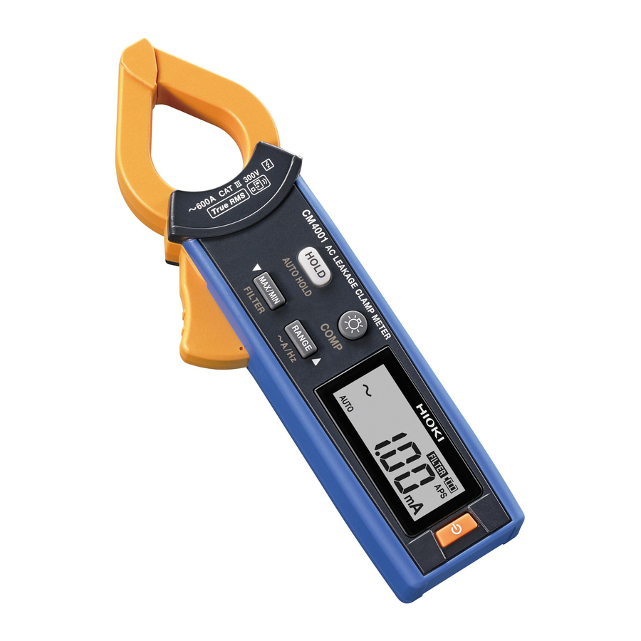
The instrument is an AC leakage clamp meter capable of true RMS value measurement of current ranging from 0.60 mA to 600.0 A using a compact, low-profile sensor. It also provides a comparator function to facilitate instantaneous pass/fail judgments.
Intended audience
This manual has been written for use by individuals who use the product or provide information about how to use the product.
In explaining how to use the product, it assumes electrical knowledge (equivalent of the knowledge possessed by a graduate of an electrical program at a technical high school).
Notations
In this document, the severity levels of risk and hazard are classified as follows.
 | Indicates an imminently hazardous situation that will result in death of or serious injury to the operator. |
 | Indicates a potentially hazardous situation that may result in death of or serious injury to the operator. |
 | Indicates a potentially hazardous situation that may result in minor or moderate injury to the operator or damage to the instrument or malfunction. |
 | Indicates an action that must not be performed. |
 | Indicates an action that must be performed. |
 | Indicates the need for caution or the presence of danger. For more information about locations where this symbol appears on instrument components, see the "Usage Notes" section, warning messages listed at the beginning of operating instructions, and accompanying the document entitled "Operating Precautions". |
 | Indicates that the instrument may be connected to or disconnected from a live conductor. |
| [ ] | The names of user interface elements on the screen are enclosed in brackets ([ ]). |
| Bold | Operation keys are printed in bold. |
The instrument screen displays the alphanumeric characters as follows.

Usage Notes
![]() Avoid dropping or jarring the instrument which could damage the jaw, adversely affecting measurement.
Avoid dropping or jarring the instrument which could damage the jaw, adversely affecting measurement.![]() Do not place any foreign object between the jaws or insert any foreign object into the gap of the sensor head. Doing so may worsen the performance of the sensor or the opening-closing operation of the sensor head.
Do not place any foreign object between the jaws or insert any foreign object into the gap of the sensor head. Doing so may worsen the performance of the sensor or the opening-closing operation of the sensor head.- Displayed values can frequently fluctuate due to induction potential even when no voltage is applied. This, however, is not a malfunction.
- The 6 A and below ranges have different sensor characteristics than the 60 A and above ranges. As a result, use of different ranges may yield different indicated values. Such differences do not represent a problem with the instrument.
- Use of the instrument should confirm not only to its specifications, but also to the specifications of all accessories, options, battery, and other equipment in use.
Names and Function of Parts


Serial No. (The 9-digit serial number indicates the year [first two digits] and the month of manufacture [next two digits]. Do not remove this sticker as the number is important.)
Strap hole (Be sure to attach the strap to prevent the instrument from dropping.)
Operation keys
| Key | Press once | Press for 1 sec. or more |
 | Retains measured value (  lights up) lights up)(Cancel: Press the HOLD key), saves measured value when using the GENNECT Cross. | Turns the auto hold function on or off. (HOLD flashes) |
 | Turns the display backlight on and off. Automatically deactivates the backlight when the instrument is not in use for 40 sec. | Turns the comparator function on or off. (COMP lights up) |
 | Switches among the maximum value, minimum value, average value, maximum peak value, minimum peak value, and current value. MAX ► MIN ► AVG ► PEAK MAX ► PEAK MIN ► ___ ___ Cancel: Press the MAX/MIN key for 1 sec. or more. | Turns the filter function on or off. (FILTER lights up) |
 | Switches among the auto range, 60.00 mA range, 600.0 mA range, 6.000 A range, 60.00 A range, and 600.0 A range. | Switches frequency measurement and current measurement. |
Power-on Option
(Turns the power on while pressing operation keys)
| Key | Function | Default value | Setting retained? |
 | Cancels the auto power save function (APS) off. | On | No |
 | Automatic backlight deactivation (on or off) | On | Yes |
 | Turns the filter function on or off when the instrument is powered on. | Off | Yes |
 | Beep (on or off) | On | Yes |
 | Displays Serial No. | – | – |
 | Displays model number, version of software, and all indicators. | – | – |
Making Measurements
To ensure that the instrument is properly operating, conduct an inspection and check instrument operation before using instrument to ensure that no damage has occurred during storage or transport. Verify that the tips of the jaws are free of damage and cracking. If there is any damage to the instrument, contact your authorized Hioki distributor or reseller for repair.
![]() To prevent an electric shock, do not touch any areas beyond the barrier while the instrument is in use.
To prevent an electric shock, do not touch any areas beyond the barrier while the instrument is in use.![]() The maximum measurement current varies with the frequency, and the current that can be measured continuously is limited. Operating the instrument at less than this limitation is referred to as derating. Do not measure currents in excess of the derating curve. Damage to the instrument or overheating can malfunction, a fire, or burn.
The maximum measurement current varies with the frequency, and the current that can be measured continuously is limited. Operating the instrument at less than this limitation is referred to as derating. Do not measure currents in excess of the derating curve. Damage to the instrument or overheating can malfunction, a fire, or burn.
Affix around the wire and check the measured value.
Leakage current measurement

- For measurement of grounded wires, clamp the instrument on one wire only (see a in the figure).
- For overall measurement, clamp the instrument on the entire circuit's wires bundled together (see b in the figure).
- To measure a single-phase 2-wire circuit, clamp both of the circuit' s wires together.
- To measure a 3-phase 4-wire circuit, clamp all 4 of the circuit' s wires bundled together. If this is not possible, carry out the measurement on the equipment's ground wire.
- Measurement may not be accurate in the cases below.
- If there is large current flowing through a nearby electric line.
- If you use the instrument to measure the waveforms on the secondary side of an inverter, or other special waveforms.
- Note that a large display count may appear momently when opening or closing the jaws. This is not an error. It may take some time for the display to return to zero. However, starting measurement before the display returns to zero will not affect measurement.
AC current measurement, frequency measurement

- Clamp the instrument on one wire only.
- Put the conductor perpendicular to the sensor.
- Correct measurement may be impossible for the case of rush current or significantly fluctuating current.
- At a low temperature, there are cases when the reading may not be around zero without any input signal. But it does not affect measurement.
- Press RANGE key for 1 sec. or more to switch frequency measurement and current measurement.
| Over-input warning (Red backlight or flashing red backlight + beep)
|
 The measured value is beyond the measurable range of current measurement. Halt measurement as the instrument is in an overinput state.
Useful Functionality
Auto hold function
When the measured value stabilizes, the value automatically retains.

Comparator function
If the present threshold value is exceeded, the instrument will sound an intermittent beep, and the display will turn red.
Changing the threshold values

Filter function
The effects of noise can be reduced by the low-pass filter.
The passband is −3 dB at 180 Hz ±30 Hz. Turn off the filter function when performing measurement of current frequencies in excess of 180 Hz. When the filter function is enabled, the indicated value may be lower than the actual value.
AC Inrush function (Inrush current measurement)
The measured value (RMS value) is retained when an inrush current is detected.
")
Repeat measurement by pressing the HOLD key.
Revert to normal measurement by pressing and holding the MAX/MIN key and RANGE key at the same time for 1 sec. or more.
The inrush range is fixed at the range during current measurement. Specifically, the inrush range is fixed to the 600.0 A range when using the auto range for current measurement and to the 600.0 mA range when using the 60 mA range for current measurement.
Auto power save (APS) function
The instrument will turn off if there is no input and no operation for about 10 min.
Wireless function (GENNECT Cross)
When the wireless function is enabled, you can review measurement data and create measurement reports on mobile devices. For more information about this functionality, see the Help function in the GENNECT Cross (application software, free of charge).
- Connect the Z3210 Wireless Adapter (option) to the instrument.
 - Step 1")
- Turn off the power switch and disconnect the clamp from the object under measurement.
- Remove the battery cover by turning screws.
- Remove the protective cap.
- Exercising care to orient
- Replace the battery cover and secure in place with the screw.
- Install the GENNECT Cross on your mobile device.
- Turn on the power switch and confirm that the wireless function is enabled.
 - Step 2")
- Launch the GENNECT Cross and pair it with the instrument.
- Select the measurement function (such as General Measurement and Waveform Graph function) and start measurement.
 - Step 1")
 - Step 2")
- The communication distance is approx. 10 m (line of sight). The distance over which data can be sent and received varies greatly depending on whether there are any obstructions between the paired instruments (for example, walls, metal barriers, etc.) and on the distance between the instrument and the floor (or ground). To ensure stable measurement, verify adequate signal strength.
- Although this application software is provided free of charge, downloading or using the application software may incur internet connection charges. Such charges are the sole responsibility of the user.
- This application software is not guaranteed to operate on all mobile devices.
Event function

By using GENNECT Cross, you can set a threshold value as desired and record data if it is exceeded. The instrument displays the number of events recorded. For more information, see the Help function in the GENNECT Cross.
Repairs, Inspections, and Cleaning
If the instrument seems to be malfunctioning, confirm that the battery is not discharged before contacting your authorized Hioki distributor or reseller.
During shipment of the instrument, handle it carefully so that it is not damaged due to a vibration or shock.
Cleaning
If the instrument becomes dirty, wipe the instrument clean with a soft cloth slightly moistened with water or a neutral detergent.
Error display
When an error is displayed on the LCD screen, repair is necessary. Please contact your authorized Hioki distributor or reseller.
[Err 1] ROM error (program)
[Err 2] ROM error (adjustment data)
[Err 4] Memory error
[Err 8] Z3210 communication error (bad connection, malfunction of Z3210 or hardware)
Replace battery

To avoid electric shock, turn off the power switch and disconnect the clamp from the object under measurement before replacing the battery
 | Fully charged. |
 | As the battery charge diminishes, black charge bars disappear, one by one, from the left of the battery indicator. |
 | The battery voltage is low. Replace the battery as soon as possible. |
 | (Flashes) The battery is exhausted. Replace the battery. |

- Remove the battery cover by turning screws.
- Replace the battery.
- Replace the battery cover and secure in place with the screw.
GENNECT Cross special site

https://gennect.net/en/cross/index
May 2020 Edition 1 CM4001A961-00 20-05H

All regional contact information
http://www.hioki.com
HEADQUARTERS
81 Koizumi
Ueda, Nagano 386-1192 Japan
HIOKI EUROPE GmbH
Rudolf-Diesel-Strasse 5
65760 Eschborn, Germany
hioki@hioki.eu
1906 EN
Edited and published by HIOKI E.E. CORPORATION
Printed in Japan
*CE declarations of conformity can be downloaded from our website.
- Contents subject to change without notice.
- This document contains copyrighted content.
- It is prohibited to copy, reproduce, or modify the content of this document without permission.
- Company names, product names, etc. mentioned in this document are trademarks or registered trademarks of their respective companies.

Documents / Resources
References
Download manual
Here you can download full pdf version of manual, it may contain additional safety instructions, warranty information, FCC rules, etc.
Advertisement


Need help?
Do you have a question about the CM4001 and is the answer not in the manual?
Questions and answers