
Subscribe to Our Youtube Channel
Related Manuals for Freescale Semiconductor NXP 56F8013


Summary of Contents for Freescale Semiconductor NXP 56F8013
- Page 1 56F8013 Socket Board for Flash Programming User Guide 56F8000 16-bit Digital Signal Controllers 56F8013SBUG Rev. 0 04/2005 freescale.com...
- Page 2 Document Revision History Version History Description of Change Rev. 0 Initial Release...
-
Page 3: Table Of Contents
Test Points............2-2 Appendix A 56F8013 Socket Board Schematics Appendix B 56F8013 Socket Board Bill of Material Table of Contents, Rev. 0 Freescale Semiconductor Preliminary... - Page 4 56F8013 Socket Board User Guide, Rev. 0 Freescale Semiconductor Preliminary...
- Page 5 Connecting the 56F8013 Socket Board ........1-2 List of Figures, Rev. 0 Freescale Semiconductor Preliminary...
- Page 6 56F8013 Socket Board User Guide, Rev. 0 Freescale Semiconductor Preliminary...
- Page 7 Appendix B, 56F8013 Socket Board Bill of Material, provides a list of the materials used on the 56F8013 Socket Board. Suggested Reading More documentation on the 56F8013 part may be found at URL: www.freescale.com Preface, Rev. 0 Freescale Semiconductor Preliminary...
- Page 8 Voltage is often shown as unless specifically positive: +3.3V noted as a negative value Blue Text Linkable on-line ...refer to Chapter 7, License Bold Reference sources, ...see: paths, emphasis http://www.freescale.com/ 56F8013 Socket Board User Guide, Rev. 0 Freescale Semiconductor Preliminary...
- Page 9 Printed Circuit Board Zero Insertion Force References The following sources were referenced to produce this manual: [1] DSP56800E Reference Manual, DSP56800ERM, Freescale Semiconductor, Inc. [2] 56F8000 Peripheral Reference Manual, MC56F8000RM, Freescale Semiconduc- tor, Inc. [3] 56F8013 Technical Data, MC56F8013, Freescale Semiconductor, Inc.
- Page 10 56F8013 Socket Board User Guide, Rev. 0 viii Freescale Semiconductor Preliminary...
-
Page 11: 56F8013 Socket Board Architecture
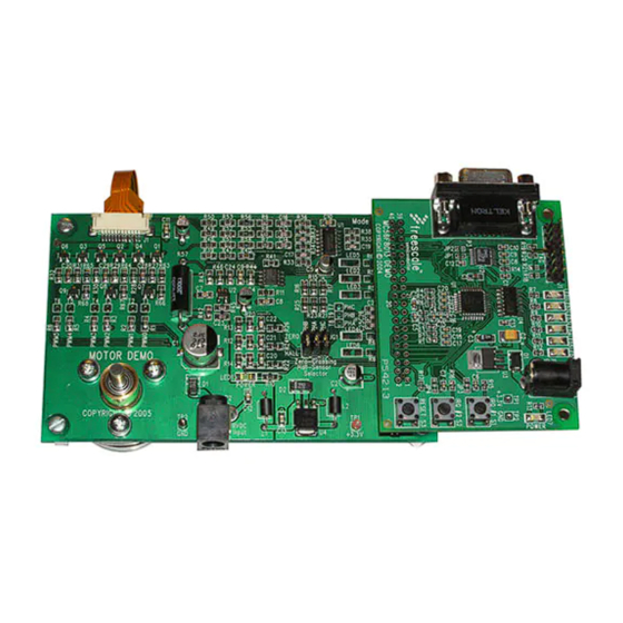
JTAG interface POD used with the 56F8013 Demonstration Board are needed to provide an operational Flash programming platform. JTAG POWER ON RESET 56F8013 Socket Board 56F8013 Demonstration Board Figure 1-1. Connecting the 56F8013 Socket Board & 56F8013 Demonstration Board Introduction, Rev. 0 Freescale Semiconductor Preliminary... - Page 12 6. Apply power to the external power supply. The green Power-ON LED on the 56F8013 Demonstration Board, LED7, and LED1 on the 56F8013 Socket Board will illuminate when power is applied correctly. 56F8013 Socket Board User Guide, Rev. 0 Freescale Semiconductor Preliminary...
-
Page 13: Technical Summary
NOTE: Parts should only be installed or removed from the LQFP-32 socket when power is not present on the 56F8013 Socket Board. Also, only one socket should have a part present at one time. Technical Summary, Rev. 0 Freescale Semiconductor Preliminary... -
Page 14: 32-Pin Pdip Socket
56F8013 part in either the U1 or U2 socket. 2.7 Test Points The 56F8013 Socket Board provides two power monitoring test points, TP1 and TP2. TP1 is connected to +3.3V and TP2 is connected to digital ground. 56F8013 Socket Board User Guide, Rev. 0 Freescale Semiconductor Preliminary... -
Page 15: Appendix A 56F8013 Socket Board Schematics
Appendix A 56F8013 Socket Board Schematics 56F8013 Socket Board Schematics, Rev. 0 Freescale Semiconductor Appendix A-1 Preliminary... - Page 16 56F8013 Socket Board User Guide, Rev. 0 Appendix A-2 Freescale Semiconductor Preliminary...
- Page 17 56F8013 Socket Board Schematics, Rev. 0 Freescale Semiconductor Appendix A-3 Preliminary...
- Page 18 56F8013 Socket Board User Guide, Rev. 0 Appendix A-4 Freescale Semiconductor Preliminary...
-
Page 19: Appendix B 56F8013 Socket Board Bill Of Material
40x2 Header SAMTEC, TSW-140-07-S-D 7x2 JTAG Header SAMTEC, TSW-107-07-S-D Test Points +3.3V Test Point KEYSTONE, 5000, RED GND Test Point KEYSTONE, 5001, BLACK Miscellaneous Rubber Feet 3M SJ5018BLKC 56F8013 Socket Board Bill of Material, Rev. 0 Freescale Semiconductor Appendix B-1 Preliminary... - Page 20 56F8013 Socket Board User Guide, Rev. 0 Appendix B-2 Freescale Semiconductor Preliminary...
- Page 21 INDEX Enhanced On-Chip Emulation EOnCE EOnce Joint Test Action Group JTAG JTAG Light Emitting Diode OnCE On-Chip Emulation OnCE Printed Circuit Board Index, Rev. 0 Freescale Semiconductor Index - 1 Preliminary...
- Page 24 LDCForFreescaleSemiconductor@hibbertgroup.com application in which the failure of the Freescale Semiconductor product could create a situation where personal injury or death may occur. Should Buyer purchase or use Freescale Semiconductor products for any such unintended...
Need help?
Do you have a question about the NXP 56F8013 and is the answer not in the manual?
Questions and answers