Table of Contents
Advertisement
Quick Links
Chipsmall Limited consists of a professional team with an average of over 10 year of expertise in the distribution
of electronic components. Based in Hongkong, we have already established firm and mutual-benefit business
relationships with customers from,Europe,America and south Asia,supplying obsolete and hard-to-find components
to meet their specific needs.
With the principle of "Quality Parts,Customers Priority,Honest Operation,and Considerate Service",our business
mainly focus on the distribution of electronic components. Line cards we deal with include
Microchip,ALPS,ROHM,Xilinx,Pulse,ON,Everlight and Freescale. Main products comprise
IC,Modules,Potentiometer,IC Socket,Relay,Connector.Our parts cover such applications as commercial,industrial,
and automotives areas.
We are looking forward to setting up business relationship with you and hope to provide you with the best service
and solution. Let us make a better world for our industry!
Contact us
Tel: +86-755-8981 8866 Fax: +86-755-8427 6832
Email & Skype: info@chipsmall.com Web: www.chipsmall.com
Address: A1208, Overseas Decoration Building, #122 Zhenhua RD., Futian, Shenzhen, China
Advertisement
Table of Contents

Related Manuals for Freescale Semiconductor NXP Freedom FRDM-KW40Z


Summary of Contents for Freescale Semiconductor NXP Freedom FRDM-KW40Z
- Page 1 Chipsmall Limited consists of a professional team with an average of over 10 year of expertise in the distribution of electronic components. Based in Hongkong, we have already established firm and mutual-benefit business relationships with customers from,Europe,America and south Asia,supplying obsolete and hard-to-find components to meet their specific needs.
-
Page 2: Table Of Contents
6. Revision history ......36 requirements of the target applications. Audience This guide is intended for system designers. © 2015 Freescale Semiconductor, Inc. All rights reserved. -
Page 3: Safety Information
(in accordance with Section 15.31(d)). The installer is responsible for ensuring that a proper antenna is employed (to not exceed the limits in this Part). FRDM-KW40Z Freescale Freedom Development Board User’s Guide, Rev. 2, 10/2015 Freescale Semiconductor, Inc. -
Page 4: Regulatory Approval For Canada (Ic Rss 210)
• Static control packaging and transportation materials and environmental systems. Disposal instructions This product may be subject to special disposal requirements. For product disposal instructions, see freescale.com/productdisposal. FRDM-KW40Z Freescale Freedom Development Board User’s Guide, Rev. 2, 10/2015 Freescale Semiconductor, Inc. -
Page 5: Frdm-Kw40Z Overview And Description
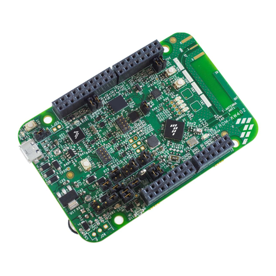
You can also connect it to the Freedom development platform. Figure 1 shows the FRDM-KW40Z development board. A similar board (not shown) uses the MKW40Z device. FRDM-KW40Z Freescale Freedom Development Board User’s Guide, Rev. 2, 10/2015 Freescale Semiconductor, Inc. - Page 6 — Receiver sensitivity is -91 dBm (for BLE applications). • Integrated PCB inverted F-type antenna and SMA RF port. • Selectable power sources. • DC-DC converter with Buck, Boost, and Bypass operation modes. FRDM-KW40Z Freescale Freedom Development Board User’s Guide, Rev. 2, 10/2015 Freescale Semiconductor, Inc.
- Page 7 Two push-button switches. • Two TSI buttons. This figure shows the main board features and Input/Output headers for the Freescale FRDM-KW40Z board: Figure 2. FRDM-KW40Z component placement FRDM-KW40Z Freescale Freedom Development Board User’s Guide, Rev. 2, 10/2015 Freescale Semiconductor, Inc.
-
Page 8: Serial And Debug Adapter
A serial port connection is available between the OpenSDAv2.1 MCU and pins PTC6 and PTC7 of the MKW40Z. NOTE To enable the Virtual COM, Debug, and MSD features, mbed drivers must be installed. Download the drivers at https://developer.mbed.org/handbook/Windows-serial-configuration. FRDM-KW40Z Freescale Freedom Development Board User’s Guide, Rev. 2, 10/2015 Freescale Semiconductor, Inc. -
Page 9: Frdm-Kw40Z Development Board
— J4 is 12-pin. — All pin headers mounted on the top side of the FRDM-KW40Z board are intended for plugging into matching receptacles on the Freedom platform development board. FRDM-KW40Z Freescale Freedom Development Board User’s Guide, Rev. 2, 10/2015 Freescale Semiconductor, Inc. - Page 10 — Pin headers mounted on the top side of the FRDM-KW40Z are intended to select between power configurations, Bypass, Buck, and Boost. Figure 4. FRDM-KW40Z board with I/O headers locations FRDM-KW40Z Freescale Freedom Development Board User’s Guide, Rev. 2, 10/2015 Freescale Semiconductor, Inc.
- Page 11 All 16 channels in the 2450 MHz band 802.15.4 frequency range 2405 2480 — All 40 channels in the 2450 MHz band BLE frequency range 2400 2480 FRDM-KW40Z Freescale Freedom Development Board User’s Guide, Rev. 2, 10/2015 Freescale Semiconductor, Inc.
- Page 12 2002/95/EC of 27 January 2003. WEEE — — — — Product complies with the EU Directive 2002/95/EC of 27 January 2003. Harmonic trap will add 1-2 dB of loss FRDM-KW40Z Freescale Freedom Development Board User’s Guide, Rev. 2, 10/2015 Freescale Semiconductor, Inc.
-
Page 13: Functional Description
Differential bidirectional RF input/output port with integrated transmit/receive switch. • “F” printed-metal antenna for a small-footprint, low-cost design. • Minimum number of RF marching components and external 50:100 balun. FRDM-KW40Z Freescale Freedom Development Board User’s Guide, Rev. 2, 10/2015 Freescale Semiconductor, Inc. - Page 14 — Load capacitors C46 and C47 provide the entire crystal load capacitance; there is no on-board trim capacitance. — The 32 kHz oscillator components are supplied, but not enabled. The 0 Ohm resistors R71 and R76 disable the 32 kHz oscillator. FRDM-KW40Z Freescale Freedom Development Board User’s Guide, Rev. 2, 10/2015 Freescale Semiconductor, Inc.
- Page 15 FRDM-KW40Z development board Figure 8. FRDM-KW40Z board’s 32 MHz reference oscillator circuit Figure 9. FRDM-KW40Z board’s optional 32.768 kHz oscillator circuit FRDM-KW40Z Freescale Freedom Development Board User’s Guide, Rev. 2, 10/2015 Freescale Semiconductor, Inc.
- Page 16 Power headers can supply either the LED, MCU, or peripheral circuits. Measure the current by inserting a current meter in place of a designated jumper. Connection configurations are described in Table FRDM-KW40Z Freescale Freedom Development Board User’s Guide, Rev. 2, 10/2015 Freescale Semiconductor, Inc.
- Page 17 J22 3-5 NOTE When configuring the Buck mode, SWD connector does not support J-Link Lite. J-Link BASE is required. It is due to the 1.8 V operating mode. FRDM-KW40Z Freescale Freedom Development Board User’s Guide, Rev. 2, 10/2015 Freescale Semiconductor, Inc.
- Page 18 FRDM-KW40Z development board Figure 11. Bypass headers Figure 12. Buck headers Figure 13. Buck Auto-Start headers Figure 14. Boost headers FRDM-KW40Z Freescale Freedom Development Board User’s Guide, Rev. 2, 10/2015 Freescale Semiconductor, Inc.
- Page 19 • The SPI Write Protect and Reset have a discrete pullup resistor. Figure 15. AT45DB021E 2-Mbit (256 KB) serial flash memory circuit FRDM-KW40Z Freescale Freedom Development Board User’s Guide, Rev. 2, 10/2015 Freescale Semiconductor, Inc.
- Page 20 • The I C can be shared with other peripherals through the J4 pin 10 and pin 12 (I C1 connectors). Figure 16. FXOS8700CQ combo sensor circuit FRDM-KW40Z Freescale Freedom Development Board User’s Guide, Rev. 2, 10/2015 Freescale Semiconductor, Inc.
- Page 21 • A single-turn potentiometer is provided. • Signal is routed through ADC0_SE. • The ADC trace can be shared with other peripherals through the J4 pin 3. FRDM-KW40Z Freescale Freedom Development Board User’s Guide, Rev. 2, 10/2015 Freescale Semiconductor, Inc.
- Page 22 • The current draw is approximately 100 mA when active. • When using the blaster as an application, assure the proper orientation. Figure 19. IR transmitter circuit FRDM-KW40Z Freescale Freedom Development Board User’s Guide, Rev. 2, 10/2015 Freescale Semiconductor, Inc.
- Page 23 VSS (GND) board ground BUZZER PTB3 (D7/CMP/int) P3V3 VREF — — — — — — PTC1 PTC1 (D14/Ana/Int) — — — — — — PTC0 PTC0 (D15/Ana/Int) FRDM-KW40Z Freescale Freedom Development Board User’s Guide, Rev. 2, 10/2015 Freescale Semiconductor, Inc.
- Page 24 P3V3 V_OUT PTC5 PTC5/TSI_CH1 PTB0/CLKOUT P5V_USB I2C1_SDA PTC3/I2C1_SDA PTB18 PTB18/CMP0_IN2 I2C1_SCL PTC2/I2C1_SCL — — — — — — — — — P5-9V_VIN Unregulated Voltage — — — FRDM-KW40Z Freescale Freedom Development Board User’s Guide, Rev. 2, 10/2015 Freescale Semiconductor, Inc.
-
Page 25: Schematic, Board Layout, And Bill Of Materials
J_VDD_1P8F Power Configuration DCDC_CFG C524 C529 C530 V_MCU C528 REG_CFG 0.1UF 0.1UF 0.1UF 0.1UF PWR_CFG PSW_CFG DCDC_CFG REG_CFG DCDC_CFG V_BATT DCDC_LP VDD_1P45F Place caps close to DUT HDR 2X3 Bypass (1.8V - 3.6V) C527 C525 C526 J_VDD_1P8F 12PF 12PF 12PF HDR 2X3 Buck (1.8V - 4.2V) PSW_CFG... - Page 26 OpenSDA Interface V_TGTMCU V_TGTMCU RESET P3V3_SDA P3V3_SDA U500 C501 C500 P3V3_SDA R503 R500 0.1UF 0.1UF 10.0K 180K VCCA VCCB C513 P3V3_SDA SDA_RST_TGTMCU_J_B P3V3_SDA 0.1UF TP501 TP_2102_A TP_2102_B TP500 VDD1 C504 10.0K LVLRST_EN C502 C509 P3V3_SDA 10uF 0.1UF SDA_SWD_EN_B_R SDA_SWD_EN NTSX2102GU8H R501 4.7K VDDA...
Need help?
Do you have a question about the NXP Freedom FRDM-KW40Z and is the answer not in the manual?
Questions and answers