Table of Contents
Advertisement
Quick Links
Advertisement
Table of Contents

Related Manuals for Freescale Semiconductor MPC5675EVB


Summary of Contents for Freescale Semiconductor MPC5675EVB
- Page 1 Msgapps1 MPC5675EVB Users Manual 473 BGA Rev B Revision 2.0 August 2010...
- Page 2 Freescale Semiconductor reserves the right to make changes without further notice to any products herein. Freescale Semiconductor makes no warranty, representation or guarantee...
-
Page 3: Table Of Contents
MPC5675EVB Users Manual Rev 2.0 July 2010 INDEX INTRODUCTION ..............................1 EVB FEATURES ..............................2 CONFIGURATION ..............................1 ........................1 OWER UPPLY ONFIGURATION 3.1.1 Power Supply Connectors ........................1 3.1.2 Power Switch (SW1) ..........................1 3.1.3 Power Status LED’s and Fuse ......................... 2 3.1.4... - Page 4 MPC5675EVB Users Manual Rev 2.0 July 2010 Index of Figures and Tables 3-1 EV ................................... 1 IGURE 3-2 2.1 .......................... 1 IGURE OWER ONNECTOR 3-3 2-L ........................1 IGURE EVER OWER ONNECTOR 3-5 EVB C ..........................4 IGURE LOCK ELECTION 3-7.
-
Page 5: Introduction
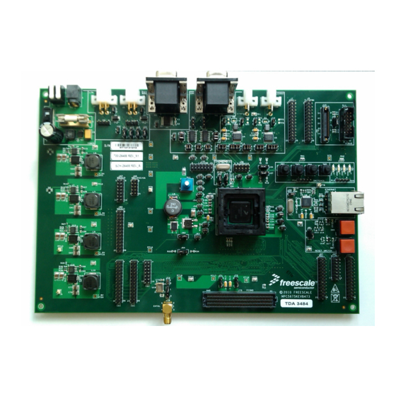
July 2010 1. Introduction This user’s manual details the setup and configuration of the Freescale Semiconductor MPC5675K Evaluation Board (hereafter referred to as the EVB). The EVB is intended to provide a mechanism for easy customer evaluation of the MPC5675K family of microprocessors, and to facilitate hardware and software development. -
Page 6: Evb Features
MPC5675EVB Users Manual Rev 2.0 July 2010 2. EVB Features The EVB provides the following key features: MCU Socket supporting the 473 BGA production package. • Single 12V external power supply input with on-board regulators to provide all of the •... -
Page 7: Configuration
MPC5675EVB Users Manual Rev 2.0 July 2010 3. Configuration This section details the configuration of each of the EVB functional blocks. Throughout this document, all of the default jumper and switch settings are clearly marked with “(D)” and are shown in blue text. -
Page 8: Power Supply Configuration
MPC5675EVB Users Manual Rev 2.0 July 2010 3.1 Power Supply Configuration The EVB requires an external power supply voltage of 12V DC, minimum 1A. This allows the EVB to be easily used in a vehicle if required. The single input voltage is regulated on-board using switching regulators to provide the necessary EVB and MCU operating voltages of 5.0V, 3.3V 1.8v and 1.2V... -
Page 9: Power Status Led's And Fuse
MPC5675EVB Users Manual Rev 2.0 July 2010 3.1.3 Power Status LED’s and Fuse When power is applied to the EVB, a green power LED’s adjacent to the voltage regulators show the presence of the 12v supply voltages. If there is no power to the MCU it is possible that either power switch SW1 is in the “OFF” position or that the fuse F1 has blown. - Page 10 MPC5675EVB Users Manual Rev 2.0 July 2010 Table 3-1 MCU Power Supply Jumpers Power Jumper Position Description Domain This supplies the IO with 3.3v 3.3V (VDD_HV_IO) 3.3 V to supply HV_DRAM with 1.8v option 3.3v/1.8v Position 2 External supplies can be added to pin 2 if extra (VDD_HV_DRAM) DRAM voltages are required.
-
Page 11: Mcu Clock Control
MPC5675EVB Users Manual Rev 2.0 July 2010 3.2 MCU Clock Control 3.2.1 Main Clock Selection (J42, J43, J73 and J74) The EVB supports three possible MCU clock sources: (1) The local 40MHz oscillator circuit (2) An 4MHz oscillator module on the EVB (U19), driving the MCU EXTAL signal... -
Page 12: Reset Boot Configuration (J69, J34, J37)
MPC5675EVB Users Manual Rev 2.0 July 2010 3.2.2 Reset Boot Configuration (J69, J34, J37) The MPC5675 has 3 boot configuration jumpers (BOOTCFG) that determines the boot location of the MCU based at POR (Power On Reset). This is shown in the table below:... - Page 13 MPC5675EVB Users Manual Rev 2.0 July 2010 Table 3-4. NEXUS Debug Connector Pinout Function Function MSEO[0] V_DEBUG MSEO[1] MDO0 MDO1 JCOMP JCOMP MDO2 MDO3 EVTI EVTO MCKO JTAG RST JTAG RST MDO4 RESET OUT RESET OUT MDO5 MDO6 MDO7 MDO8...
-
Page 14: Can Configuration (J21, J22, J29, J30, J31)
MPC5675EVB Users Manual Rev 2.0 July 2010 3.4 CAN Configuration (J21, J22, J29, J30, J31) The EVB has 2x NXP TJA1041T high speed CAN transceiver on the MCU CAN-A and CAN-B channels. These can operate with 5v or 3.3v I/O from the MCU. For flexibility, the CAN transceiver I/O is connected to a standard 0.1”... -
Page 15: Rs232 Configuration (J5,J6,J15, J16, J23)
MPC5675EVB Users Manual Rev 2.0 July 2010 3.5 RS232 Configuration (J5,J6,J15, J16, J23) The EVB has a single MAX3223 RS232 transceiver device, providing RS232 signal translation for the MCU SCI channels A and B. Each of the two RS232 outputs from the MAX3223 device is connected to a DB9 connector, allowing a direct RS232 connection to a PC or terminal. -
Page 16: Lin Configuration (J5, J6, J16, J23,J18,J17,J19,J20)
MPC5675EVB Users Manual Rev 2.0 July 2010 LIN Configuration (J5, J6, J16, J23,J18,J17,J19,J20) The EVB is fitted with two Freescale MCZ33661EF LIN transceivers. The LINFLEX module incorporates a UART mode, and as such, the LIN transceivers are connected to the TX and RX signals of SCI via UART A and B. -
Page 17: Flexray Configuration (J19, J27, J25, J26, J28)
MPC5675EVB Users Manual Rev 2.0 July 2010 3.6 FlexRAY Configuration (J19, J27, J25, J26, J28) The EVB is fitted with 2 FlexRAY physical interfaces connected to MCU FlexRAY channels A and B. Jumpers J19 and J27 are provided to route the respective MCU signals to the physical interfaces as described below. - Page 18 MPC5675EVB Users Manual Rev 2.0 July 2010 Table 3-10 Flexray Control Jumpers (J26, J28) Jumper Position Description Legend J27 (Flex-A) FITTED (D) Flexray-A interface BGE signal is pulled to VIO Posn 1-2 REMOVED Flexray-A interface BGE signal is unterminated J27 (Flex-A)
-
Page 19: Ethernet
MPC5675EVB Users Manual Rev 2.0 July 2010 3.7 Ethernet The EVB is fitted with a National Semiconductor DP8348C Ethernet physical interface (U8) and a RJ45 connector with integrated activity LED’s and magnetics (J51). The National Semiconductor DP8348C physical interface is connected to the MII on the MPC5675. -
Page 20: Pismo Dramc Connector
MPC5675EVB Users Manual Rev 2.0 July 2010 3.8 PISMO DRAMC Connector The PISMO02-00040 board connector provided by Samtec is available for connecting DDR1, DDR2 or mDDR (LPDDR) to the EVB. Appropriate RAM daughter cards are available from Micron. Such as... -
Page 21: Default Jumper Summary Table
MPC5675EVB Users Manual Rev 2.0 July 2010 4. Default Jumper Summary Table 473BGA ONLY The following table details the DEFAULT jumper configuration of the EVB as explained in detail in section 3. 473BGA ONLY Table 4-1 Default Jumper Positions Default Setting... - Page 22 MPC5675EVB Users Manual Rev 2.0 July 2010 FlexrayA data signals are connected to MCU FlexrayA control signals are on FlexrayB data signals are connected to MCU FlexrayB control signals are on FlexrayA decoupling capacitor is disabled FlexrayA decoupling capacitor is disabled...
-
Page 23: User Connector Descriptions
MPC5675EVB Users Manual Rev 2.0 July 2010 5. User Connector Descriptions This section details the pinout of the EVB user connectors. The connectors are 0.1 inch pitch turned pin headers and are located at various locations on the EVB. They are grouped by port functionality and the PCB legend shows the respective port number adjacent to each pin. -
Page 24: Adc 2/3 (Connector J47)
MPC5675EVB Users Manual Rev 2.0 July 2010 5.1.3 ADC 2/3 (Connector J47) Table 5-3 ADC 2/3 Connector Pinout (J47) Function Function ADC2_AN0 ADC3_AN0 ADC2_AN1 ADC3_AN1 ADC2_AN2 ADC3_AN2 ADC2_AN3 ADC3_AN3 ADC2_ADC3_AN ADC2_ADC3_AN ADC2_ADC3_AN ADC2_ADC3_AN 5.1.4 EBI (Connector J66, J69, J70) Table 5-4 EBI Connector Pinout (J66) -
Page 25: Nmi / Fcc / Cg (J45)
MPC5675EVB Users Manual Rev 2.0 July 2010 Function Function EBI_D6 / EBI_ADD22 EBI_D22 EBI_D7 / EBI_ADD23 EBI_D23 EBI_D8 / EBI_ADD24 EBI_D24 EBI_D9 / EBI_ADD25 EBI_D25 EBI_D10 / EBI_ADD26 EBI_D26 EBI_D11 / EBI_ADD27 EBI_D27 EBI_D12 / EBI_ADD28 EBI_D28 EBI_D13 / EBI_ADD29... -
Page 26: Flexpwm (J8)
MPC5675EVB Users Manual Rev 2.0 July 2010 5.1.7 FLEXPWM (J8) Table 5-9 FLEXPWM Connector Pinout (J8) Function Function FLEXPWM0_A0 FLEXPWM1_A0 FLEXPWM0_A1 FLEXPWM1_A1 FLEXPWM0_A2 FLEXPWM1_A2 FLEXPWM0_A3 FLEXPWM1_A3 FLEXPWM0_B0 FLEXPWM1_B0 FLEXPWM0_B1 FLEXPWM1_B1 FLEXPWM0_B2 FLEXPWM1_B2 FLEXPWM0_B3 FLEXPWM1_B3 FLEXPWM0_X0 FLEXPWM1_X0 FLEXPWM0_X1 FLEXPWM1_X1 FLEXPWM0_X2 FLEXPWM1_X2... -
Page 27: Linflex / Flexcan (J35)
MPC5675EVB Users Manual Rev 2.0 July 2010 5.1.10 LINFLEX / FLEXCAN (J35) Table 5-12 LIN / CAN Connector Pinout (J35) Function Function LIN0_TXD LIN1_TXD LIN0_RXD LIN1_RXD CAN0_TXD CAN1_TXD CAN0_RXD CAN1_RXD 5.1.11 DSPI (J7) Table 5-13 DSPI Connector Pinout (J7) Function... -
Page 28: Known Bugs List
MPC5675EVB Users Manual Rev 2.0 July 2010 6. Known Bugs List MPC5675EVB Page 21 of 29... - Page 29 MPC5675EVB Users Manual Rev 2.0 July 2010 Appendix A - EVB Schematics MPC5675EVB Page A-1...
-
Page 30: Mpc5675Evb
MPC5675EVB Users Manual Rev 2.0 July 2010 MPC5675EVB Page A-2... -
Page 31: Mpc5675Evb
MPC5675EVB Users Manual Rev 2.0 July 2010 MPC5675EVB Page A-3... -
Page 32: Mpc5675Evb
MPC5675EVB Users Manual Rev 2.0 July 2010 MPC5675EVB Page A-4... -
Page 33: Mpc5675Evb
MPC5675EVB Users Manual Rev 2.0 July 2010 MPC5675EVB Page A-5... -
Page 34: Mpc5675Evb
MPC5675EVB Users Manual Rev 2.0 July 2010 MPC5675EVB Page A-6... -
Page 35: Mpc5675Evb
MPC5675EVB Users Manual Rev 2.0 July 2010 MPC5675EVB Page A-7... -
Page 36: Mpc5675Evb
MPC5675EVB Users Manual Rev 2.0 July 2010 MPC5675EVB Page A-8... -
Page 37: Mpc5675Evb
MPC5675EVB Users Manual Rev 2.0 July 2010 MPC5675EVB Page A-9... -
Page 38: Mpc5675Evb
MPC5675EVB Users Manual Rev 2.0 July 2010 MPC5675EVB Page A-10... -
Page 39: Mpc5675Evb
MPC5675EVB Users Manual Rev 2.0 July 2010 MPC5675EVB Page A-11... - Page 40 MPC5675EVB Users Manual Rev 2.0 July 2010 MPC5675EVB Page A-12...
-
Page 41: Mpc5675Evb
MPC5675EVB Users Manual Rev 2.0 July 2010 MPC5675EVB Page A-13... -
Page 42: Mpc5675Evb
MPC5675EVB Users Manual Rev 2.0 July 2010 MPC5675EVB Page A-14... -
Page 43: Mpc5675Evb
MPC5675EVB Users Manual Rev 2.0 July 2010 MPC5675EVB Page A-15... -
Page 44: Mpc5675Evb
MPC5675EVB Users Manual Rev 2.0 July 2010 MPC5675EVB Page A-16... -
Page 45: Mpc5675Evb
MPC5675EVB Users Manual Rev 2.0 July 2010 MPC5675EVB Page A-17...
Need help?
Do you have a question about the MPC5675EVB and is the answer not in the manual?
Questions and answers