Table of Contents
Advertisement
Quick Links
Advertisement
Table of Contents

Related Manuals for EOS Vision


Summary of Contents for EOS Vision
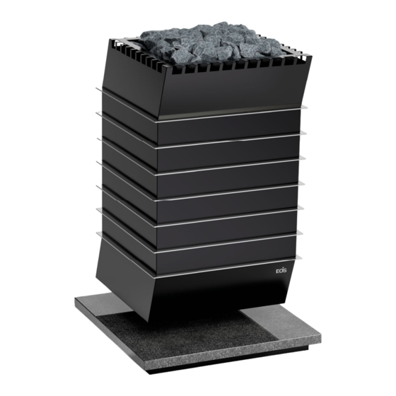
- Page 1 EOS Vision Heater for Sauna Cabins Installation and Operating Instructions...
-
Page 2: Documentation
Result of a step Table title Title of figure ≤ ≥ Less than or equal to, greater than or equal to Revision history Date Version Description 23 Jan. 2023 01.00 First version EN-2 Installation and Operating Instructions - EOS Vision... -
Page 3: Table Of Contents
Establishing an electrical connection ..........EN-35 Heating period limitation..............EN-35 5 Commissioning ....................EN-36 Filling with stones ................EN-36 Starting the heater................EN-37 Switching the heater on remotely ..........EN-37 Water splash.................... EN-38 EOS Vision - Installation and Operating Instructions EN-3... - Page 4 6 Service and maintenance................EN-39 Cleaning....................EN-39 Sauna stones ................... EN-40 Replacing the tubular heating elements ........EN-41 Troubleshooting ..................EN-46 7 General terms and conditions of service ........... EN-47 8 Disposal ......................EN-50 EN-4 Installation and Operating Instructions - EOS Vision...
-
Page 5: General Safety Instructions
The sauna heater may not be placed on a floor made of easily flammable material (e.g. laminate or synthetic flooring). Ceram- ic tiles are recommended as a flooring option. EOS Vision - Installation and Operating Instructions EN-5... - Page 6 This control unit is fixed to a suitable location on the cabin's external wall, and the corresponding tempera- ture sensor according to the installation instructions that ac- company the control units inside the sauna cabin. EN-6 Installation and Operating Instructions - EOS Vision...
-
Page 7: Operator Instruction
Spending time in a sauna cabin can lead to serious health risks or even death for persons with health impairments. Persons with health impairments who spend time in a sauna must consult a doctor before entering a sauna cabin. EOS Vision - Installation and Operating Instructions EN-7... - Page 8 Children must be supervised to ensure they do not play with with reduced mental capacity the unit. Children and persons who have not received proper instruction must not clean or service the system. EN-8 Installation and Operating Instructions - EOS Vision...
-
Page 9: Safety Levels
For an overview of the standards that were observed during design and construction of the sauna heaters, please refer to the individual product’s technical data sheet that can be downloaded from www.eos-sauna.com. Local regulations also apply to the installation and operation of heating, sauna, and steam room systems. -
Page 10: Identification
Identification Identification EOS Vision/Vision Stone is an electrically heated sauna heater for Finnish mode available in a variety of output capacities. Requirements for operation The heater must be operated with one of the following control units: EmoStyle series EmoTec series ... -
Page 11: Scope Of Delivery
The base plate is made of different stone variations depending on the model. The following parts are included in the scope of delivery: A Vision sauna heater with base plate C Connecting cable, 8 m, pre-installed B Sauna stones, 40 kg D Installation and Operating Instruc- Caliber 50–100 mm... -
Page 12: Technical Data
3 x 16 A All line cross-section specifications are the minimum cross-sections for the copper line. The sauna heater must be operated by a sauna control unit. *) Not required for Compact D18/H18 control units. EN-12 Installation and Operating Instructions - EOS Vision... -
Page 13: Intended Use
This heater is intended solely for the purpose of heating sauna cabins, together with a suitable control unit. EOS Vision/Vision Stone is suitable for commercial and private use. The heater is not suitable for outdoor use. It must be operated only inside buildings and may not be exposed to envi-... - Page 14 The first time the cabin is heated, you may notice a slight odour result- ing from the evaporation of consumables used in the manufacturing processes. Air out your cabin once it has been heated and before using the sauna. EN-14 Installation and Operating Instructions - EOS Vision...
-
Page 15: Installation
Installation Installation This chapter describes how to install Vision. Prior to installing the unit, air inlets and outlets must be installed in the cabin. It may be necessary to mount additional fans in the inlets/outlets. All protective films must be removed. -
Page 16: Installation Site
6 cm 60 cm 6 cm 60 cm 6 cm A Cabin ceiling D Heater guard rail B Temperature sensor E Heater C Cabin wall F Air inlet Dimensions in the cabin EN-16 Installation and Operating Instructions - EOS Vision... -
Page 17: Air Inlets And Outlets
If the heating process takes a long time, the underlying reason is that the sauna heater receives insufficient air. A minimum of 5 times the cabin volume of air per hour must be exchanged. EOS Vision - Installation and Operating Instructions EN-17... - Page 18 Supply air from below (figure on the left) and from the side (figure on the right) Air outlet The air outlet must meet the following criteria: Position: across from the heater Height: 30–50 cm above the cabin floor EN-18 Installation and Operating Instructions - EOS Vision...
-
Page 19: Temperature Sensor
For placement, see Dimensions in the cabin, EN-16. NOTICE Malfunction due to damaged temperature sensor The temperature sensor is protected by its housing. Ensure that the housing and the temperature sensor are not damaged during operation. EOS Vision - Installation and Operating Instructions EN-19... -
Page 20: Heater Guard Rail
Unpacking the heater and base plate Remove the heater and base plate packaging. Leave the heater and base plate on the pallet. Remove all transport locks and protective films in the heater. EN-20 Installation and Operating Instructions - EOS Vision... - Page 21 Lift the heater from the pallet and place it on the underlay in front of the base plate. The rear side of the heater must face upward. EOS Vision - Installation and Operating Instructions EN-21...
-
Page 22: Connecting Cable
230 V 1N ~), the following step is required: Changing the connecting cable (optional), EN-24 Laying the connecting cable Route the connecting cable through the base of the base plate. EN-22 Installation and Operating Instructions - EOS Vision... - Page 23 Drilling template for concealed connecting cable Route the connecting cable through the base of the base plate. Route the connecting cable under the cabin floor with a suitable protec- tive cover. EOS Vision - Installation and Operating Instructions EN-23...
- Page 24 Feed the connecting cables through the cable screw connection out from the heater. Feed the new connecting cable through the cable screw connection on the terminal box and tighten the cable screw connection. EN-24 Installation and Operating Instructions - EOS Vision...
- Page 25 Feed the connecting cable through the opening in the heater base. Fix the covers of the terminal box in place and screw in and tighten the screw. Put the back panel in place and screw in and tighten the screws. EOS Vision - Installation and Operating Instructions EN-25...
-
Page 26: Installing The Heater
The openings for the cable feed opening in the heater base and in the base of the base plate must point in the same direction. Tighten the connecting cable if necessary. Loosen the screws in the lower back panel and remove it. EN-26 Installation and Operating Instructions - EOS Vision... - Page 27 The heater base must be accessible. Screw the screws into the holes in the heater base and tighten them with a ring or socket spanner. Put the lower housing and lower back panel in place. EOS Vision - Installation and Operating Instructions EN-27...
-
Page 28: Electrical Installation
The sauna control unit and the heater must be connected as shown in the circuit diagrams. Please observe the installation and operating instructions for the sauna control unit. See also 2.5 Technical data, EN-12. EN-28 Installation and Operating Instructions - EOS Vision... -
Page 29: Connecting To 400 V 3N
Connection diagram 9, 10, 12* and 15* kW Connection with the Econ control unit is possible only at 9 kW. *) Only for connecting to Compact D18/H18 control units. EOS Vision - Installation and Operating Instructions EN-29... - Page 30 D Power extension unit (LSG) unit safety temperature limiter F Mains connection for power exten- sion unit Connection diagram 12* and 15* kW *) Not for connecting to Compact D18/H18 control units. EN-30 Installation and Operating Instructions - EOS Vision...
- Page 31 D Power extension unit (LSG) F Mains connection for power extension safety temperature limiter unit Connection diagram 12* and 15* kW, double circuit *) Not for connecting to Compact D18/H18 control units. EOS Vision - Installation and Operating Instructions EN-31...
-
Page 32: Connecting To 230 V 1N
Connection diagram * Cable cross-sections must correspond to the sauna heater output: 9 kW – 6 mm² A distributor for the 1-phase connection can be purchased separately: Item no. 94.2689 EN-32 Installation and Operating Instructions - EOS Vision... -
Page 33: Internal Wiring
4.2.3 Internal wiring 9 and 10 kW heater output ) r G Internal wiring 9 and 10 kW 9 kW = 6x 1500 W 10 kW = 6x 1666 W EOS Vision - Installation and Operating Instructions EN-33... - Page 34 Internal wiring 12 and 15 kW (with LSG) 12 kW = 6x 2000 W 15 kW = 6x 2500 W **) Not for connecting to Compact D18/H18 control units. EN-34 Installation and Operating Instructions - EOS Vision...
-
Page 35: Establishing An Electrical Connection
24-hour period before an independent restart can take place. Units used in private saunas must be limited to an operating time of 6 hours, and an automatic restart is not permitted. EOS Vision - Installation and Operating Instructions EN-35... -
Page 36: Commissioning
Start the heater only if it has been filled with stones. Ensure stones with the correct caliber are used: 50–100 mm. Place the stones loosely in the rock store. EN-36 Installation and Operating Instructions - EOS Vision... -
Page 37: Starting The Heater
Switching the heater on remotely If you switch on the heater remotely, ensure that no objects are placed on the heater. A suitable safety system, for example EOSafe D/L, can be used to prevent this. EOS Vision - Installation and Operating Instructions EN-37... -
Page 38: Water Splash
10 minutes before starting the next one. This time is needed for the sauna stones to reheat. Recommendation: During a water splash, no more than approx. 10 cL of water per m³ cabin volume should be vaporised. EN-38 Installation and Operating Instructions - EOS Vision... -
Page 39: Service And Maintenance
Remove lint and dust from openings and heat reflectors. Openings can easily become blocked with lint and dust as fresh air is drawn in. This limits the air convection ability of the heater and could lead to impermissible temperatures. EOS Vision - Installation and Operating Instructions EN-39... -
Page 40: Sauna Stones
100 mm Rinse all stones with cold water. Place the stones loosely so that there is enough space between them for air to circulate sufficiently. Filling the rock store, EN-37 EN-40 Installation and Operating Instructions - EOS Vision... -
Page 41: Replacing The Tubular Heating Elements
Move the heater only by the base plate. Do not lift the heater. If necessary, pull the heater away from the wall if the rear of the heater cannot be reached. EOS Vision - Installation and Operating Instructions EN-41... - Page 42 Loosen the screw on the cover of the terminal box and remove the cov- Loosen the connecting cable from the connection terminals. Feed the connecting cables through the cable screw connections out from the terminal box. EN-42 Installation and Operating Instructions - EOS Vision...
- Page 43 Pull out the terminal box with the heating coil. To do this, first press the heating coil down slightly and then pull it out forwards. Check drip trays below the heating coil for dirt and debris and clean if necessary. EOS Vision - Installation and Operating Instructions EN-43...
- Page 44 Fix the heating element with the serrated washers and the fixing nuts. Plug in the flat plug. Check the wiring on all heating elements before reclosing the termi- nal box and setting up the heater. EN-44 Installation and Operating Instructions - EOS Vision...
- Page 45 Put on the covers of the terminal box and the rear panel of the heater. Move the heater back into its original position. Place the stones in the rock store. Switch on the fuses of the heater. EOS Vision - Installation and Operating Instructions EN-45...
-
Page 46: Troubleshooting
The position of the temperature sensor Check the position of the temperature in the cabin is not optimal. sensor and adjust as needed. See 3.1.3 Temperature sensor, EN-19. EN-46 Installation and Operating Instructions - EOS Vision... -
Page 47: General Terms And Conditions Of Service
The customer shall provide assistance free of charge to the manufacturer in rendering services. In the case of a warranty claim, the manufacturer shall provide spare parts necessary for servicing free of charge. EOS Vision - Installation and Operating Instructions EN-47... - Page 48 Only original spare parts may be used within the warranty period. Service visits made by third parties shall require a written order issued by our service department. EN-48 Installation and Operating Instructions - EOS Vision...
- Page 49 The manufacturer’s General Terms and Conditions of Business, in the ver- sion available at www.eos-sauna.com/agb, shall apply in addition to the foregoing terms and conditions of service. EOS Vision - Installation and Operating Instructions...
-
Page 50: Disposal
Electronic waste Electronic waste must be disposed of at the designated local collection point for electronic waste. Additional disposal instructions for commercial users (DE only) You can find further disposal instructions under www.eos-sauna.com/recycling EN-50 Installation and Operating Instructions - EOS Vision... - Page 52 made in Germany Stand 04/2023 Druck-Nr. 2902 5212 All rights reserved.
Need help?
Do you have a question about the Vision and is the answer not in the manual?
Questions and answers