Advertisement
Quick Links
FLUID CONTROL DIVISION
Parker Hannifin Corporation
95 Edgewood Avenue
New Britain, CT 06051
Telephone (860) 827-2300
Fax (860) 827-2384
WARNING
GENERAL SAFETY INSTRUCTIONS BEFORE INSTALLATION
FAILURE OR IMPROPER SELECTION OR IMPROPER USE OF THE PRODUCTS AND/OR SYSTEMS
DESCRIBED HEREIN OR RELATED ITEMS CAN CAUSE DEATH, PERSONAL INJURY AND PROPERTY
DAMAGE.
The conduit coil contains a green "grounding" wire that must be secured to a proper ground location.
DO NOT cut off the green ground wire. Doing so could negate a proper ground path and leave the valve assembly
unprotected or "hot".
This document and other information from Parker Hannifin Corporation, its subsidiaries and authorized distributors
provide product and/or system options for further investigation by users having technical expertise. It is important that
you analyze all aspects of your application, including consequences of any failure, and review the information
concerning the product or system in the current product catalog. Due to the variety of operating conditions and
applications for these products or systems, the user, through its own analysis and testing, is solely responsible for
making the final selection of the products and systems and assuring that all performance, safety and warning
requirements of the application are met. Usage of the device in a manner that is contrary to these Operating
Instructions or the application conditions and specification provided in the Catalog is improper and will void your
warranty.
The products described herein, including without limitation, product features, specifications, designs, availability and
pricing, are subject to change by Parker Hannifin Corporation and its subsidiaries at any time without notice.
Carefully read installation, operation and maintenance procedures prior to installing or servicing valve.
Do not use valve as a safety shut-off valve when making repairs.
Do not install a valve or attempt to repair a valve before depressurizing system down to atmospheric pressure and
removing electrical voltage.
Care must be taken to ensure the proper use of the valve and that the valve materials selected are suitable for the
media being handled. Parker assumes no liability for damage caused by improper material selection in the case of
corrosion from aggressive media.
Caution: Do not, at any time, make any alteration or modifications to any valve without the express and written
approval of Parker's Fluid Control Division.
Installation, Operating & Maintenance Instructions
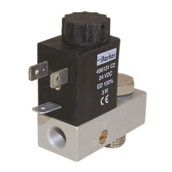
3-Way Normally Closed Direct Acting Solenoid Valves
Valve Types: U131B01, U131B02, 131B03, 131B04
!
IOM BANJ01
(Rev 0810)
1/8" & 1/4"
Advertisement

Related Manuals for Parker U131B01


Summary of Contents for Parker U131B01
- Page 1 Care must be taken to ensure the proper use of the valve and that the valve materials selected are suitable for the media being handled. Parker assumes no liability for damage caused by improper material selection in the case of corrosion from aggressive media.
-
Page 2: Manual Override
Description These valves are direct operated 3-way normally closed solenoid models. The valves mount directly to a piston or diaphragm actuator enclosure including process control valves and angle seat valves. The 3-way valves are offered in anodized aluminum body construction. Valves may be ordered with either DIN or Conduit integrated coils for ordinary locations. -
Page 3: Electrical Connections
Installation Instructions Prior to installing the solenoid valve, depressurize the pipes and clean them internally to avoid particles entering the system (tape sealant, thread compound). The valves may be mounted in any position. Mounting position and pressure limits: Valve with DIN or Conduit Coil: The valve is mounted directly to the actuator by screwing the banjo bolt directly into actuator inlet port and is designed to operate in any position. -
Page 4: Maintenance
ELECTRICAL CONNECTIONS (continued) : Turn off electrical power before connecting the valve to the power source. ARNING If the coil assembly is located in an inconvenient orientation, it may be reoriented to facilitate installation. Loosen coil assembly nut, rotate coil assembly to the desired position, and then retighten the nut with an input torque of 4.0 to 5.0 in-lbs. - Page 5 EC directives. The data supplied in the Parker catalogs and general Installation, Operating & Maintenance Instructions are to be consulted and pertinent accident prevention regulations followed during product installation and use. Any unauthorized work performed on the product by the purchaser or by third parties can impair its function and relieves Parker Hannifin of all warranty claims and liability for any misuse and resulting damage.
-
Page 6: Troubleshooting
TROUBLE SHOOTING Symptom Procedure Valve fails to operate or is sluggish. 1. Check electrical supply with voltmeter. Voltage must agree with coil rating. 2. If supply voltage too low, locate and correct cause of low voltage. Should exceed 85% of rated voltage. 3.