
Related Manuals for Parker IQAN-XC21


Summary of Contents for Parker IQAN-XC21
- Page 1 IQAN-XC21 Instruction book Publ no HY33-8410-IB/UK Edition 2015-02-18 www.comoso.com...
-
Page 2: Table Of Contents
IQAN-XC21 ........ - Page 3 Appendix C ........... 29 Dimensioning of the IQAN-XC21 ....... . . 29 Instruction book, IQAN-XC21 www.comoso.com...
-
Page 4: Introduction
Contact the manufacturer if there is anything you are not sure about or if you have any questions regarding the product and its handling or maintenance. The term "manufacturer" refers to Parker Hannifin Corporation. Instruction book, IQAN www.comoso.com... -
Page 5: Overview Of Relevant Documentation
Overview of relevant documentation Introduction Overview of relevant documentation The following publications are relevant for users of this product. The main documentation contains information that is not found elsewhere. The additional documentation contains product information in a compact format, for details on the information found in those documents, consult this manual. -
Page 6: Precautions
Read This Precautions Precautions Work on the hydraulics control electronics may only be carried out by trained personnel who are well-acquainted with the control system, the machine and its safety regulations. ARNING Make sure that you have sufficient knowledge before designing, modifiying or servicing the control system. -
Page 7: Start-Up, Maintenance, And Diagnostics
Read This Precautions Start-up, maintenance, and diagnostics For all personnel carrying out installation, commissioning, maintenance or troubleshooting. ARNING Work on the hydraulics control electronics may only be carried out by trained personnel who are well-acquainted with the control system, the machine and its safety regulations. -
Page 8: Product Description
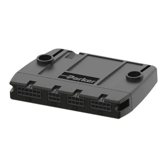
IQAN-XC21 Product description Product description IQAN-XC21 The IQAN-XC21 is a stackable, flexible expansion module designed as a signal input module for use in cab, using 12/24 Vdc power supply. Two IQAN-XC21 modules I/O overview Voltage inputs The IQAN-XC21 module has eight (8) voltage inputs VIN-A thru VIN-H for connection of 0-5 Vdc signals. -
Page 9: Can Related Functions
CAN related functions The master uses the CAN-bus (CAN = Controller Area Network) to communicate with the modules. The CAN-bus is a robust communication protocol that is widely used and well proven within the automotive industry. Instruction book, IQAN-XC21 www.comoso.com... -
Page 10: Safety
Internal diagnostics Safety Safety Internal diagnostics The module performs a number of self-checks that improve safety. Checks include monitoring of voltage supplies, checksums on memory and a watchdog that monitors software execution. The module is using a real time operating system which supervises software execution. -
Page 11: Mounting
Mounting Mounting the module IQAN-XC21 is designed as a in cab module and is meant to be mounted in a protected environment. The housing is designed for stacking multiple modules, providing a high density of I/O in a small footprint. -
Page 12: Installation
0.76µm version) Recommended ø1.85mm max (AWG 20, 22, 24) cable OTICE Tin plated contacts must NOT be used, the header has gold plated terminals and this must be matched on the receptacle to fulfill all environmental requirements. Instruction book, IQAN-XC21 www.comoso.com... -
Page 13: Connector C1 Pin Assignments
Connector C3 pin assignments Pin No. Function Alt. Function Remark -VREF-B VIN-E DIN-Q Lever signal Z1p VIN-G DIN-S Lever signal Z2p +VREF-B (+5V) Max 70 mA VIN-F DIN-R Lever signal Z1s VIN-H DIN-T Lever signal Z2s Instruction book, IQAN-XC21 www.comoso.com... -
Page 14: Connector C4 Pin Assignments
DOUT-C FIN-E PCNT-E PWMIN-C DIN-D DOUT-D FIN-F PCNT-F DIN-E DOUT-E FIN-G PCNT-G DIN-F DOUT-F FIN-H PCNT-H DIN-G DOUT-G FIN-I PCNT-I DIN-H DOUT-H FIN-J PCNT-J DIN-I DIN-J FIN-A PCNT-A DIN-K +DPCNT-A FIN-B PCNT-B +DFIN-A DIN-L -DPCNT-A -DFIN-A Instruction book, IQAN-XC21 www.comoso.com... -
Page 15: Supply Voltage
Supply voltage Supply voltage Before any installation of the IQAN system can take place, make sure the ignition lock is turned off and the battery is disconnected. Emergency stop Make sure an Emergency Stop disconnecting the power supply, is easily accessible at any time. -
Page 16: Addressing/Terminating
Addressing/terminating Addressing/terminating Addressing Each IQAN expansion module will have a specific address, enabling the master module to communicate with the modules through the CAN-bus. When operating, the system distinguishes between different modules by first verifying the module type and secondly, through the modules having unique addresses. EXAMPLE If having an expansion module with address 0, the system will denote this one as [module type]-A0, The letter "A"... -
Page 17: Reference Voltage, Vref
Reference voltage, VREF Reference voltage, VREF The IQAN module is internally equipped with a voltage regulator to generate the reference voltage VREF. The standard reference voltage will feed different kinds of sensors and potentiometers. IQAN module +VREF -VREF VREF positions. OTICE It is strongly recommended to use the module’s -VREF and +VREF to all sensors and potentiometers that are connected to the module inputs. -
Page 18: Voltage Inputs
Voltage inputs Voltage inputs Connecting sensors to the voltage inputs The sensor signal range must be 0-5 Vdc. To detect signal errors such as short circuits or interruptions the active signal range be within 0.5-4.5 Vdc. Error detection range Active signal range Error detection range Active signal range. -
Page 19: Connecting A 2-Wire Temperature Sensor To Voltage In
Voltage inputs Connecting a 2-wire temperature sensor to voltage in When you connect a PTC (positive temperature coefficient) temperature sensor you may need to use a pull up resistor on the input signal. Please check the technical data for your specific temperature sensor. EXAMPLE Connect the negative terminal of the temperature sensor to -VREF, and the signal to VIN-X. -
Page 20: Connecting Switches To The Voltage Inputs Using +Bat
Voltage inputs Connecting switches to the voltage inputs using +BAT It is recommended to connect system voltage +BAT to the input through a switch in order to reserve 5Vdc VREF for sensors and potentiometers. EXAMPLE Connect the positive and negative terminals of the switch to supply or the unit’s +BAT, and DIN-X, respectively. -
Page 21: Frequency Inputs
Frequency inputs Frequency inputs Connecting sensors to the frequency inputs Frequency inputs can operate in 2 modes. Speed which is frequency and position which is a pulse count. For the frequency ranges and trigger levels, see Appendix A. Simple frequency sensor The positive terminal of the frequency sensor is connected to the +VREF and the negative terminal to the -VREF respectively. -
Page 22: Directional Frequency Inputs
Directional frequency inputs Directional frequency inputs Connecting sensors to the directional frequency inputs Directional frequency inputs can operate in 2 modes. Speed which is frequency and position which is a pulse count. For the frequency ranges and trigger levels, see Appendix A. -
Page 23: Pwm Inputs
PWM inputs PWM inputs Connecting PWM sensor The positive terminal of the PWM sensor is connected to the +VREF and the negative terminal to the -VREF respectively. The sensor signal is connected to a PWMIN position. If the current consumption for the sensor exeeds the maximum load for the VREF, the sensor could be connected to the +BAT/-BAT positions. -
Page 24: Low-Side Digital Outputs
Low-side digital outputs Low-side digital outputs The low-side digital outputs are designed to drive small loads, e.g. lamps and buzzers. Low-side digital outputs work by grounding a signal through the module. See Appendix A for maximum loads per output. EXAMPLE Connect the lamp to the low-side digital outputs using a DOUT(LS) position, and the +BAT, as supply. -
Page 25: Start-Up
Start-up procedures Start-up Start-up Start-up procedures This chapter contains instructions for action to be taken in connection with the initial start. ARNING Risk of injury! If the control system is not fitted properly, the machine could move uncontrollably. The machine’s engine shall not be started before the control system is completely fitted and its signals are verified. -
Page 26: System Diagnostics
The location of the LED indicators on the IQAN module. The LED indicates power on. The yellow/red LED, will be blinking red when an error has been detected. For further information about the error messages, see Appendix B. Instruction book, IQAN-XC21 www.comoso.com... -
Page 27: Iqan-Xc21 Technical Overview
IQAN-XC21 Technical Overview Appendix A Appendix A IQAN-XC21 Technical Overview Absolute Maximum Ratings Ambient temperature -30 to 70 °C Storage temperature -40 to 85 °C Voltage supply on +BAT 6.5 to 36 V Voltage on any pin with respect to -BAT 36 V a.The “Absolute Maximum Ratings”... - Page 28 IQAN-XC21 Technical Overview Appendix A Sensor supply - VREF Number of VREF Output voltage 5 V ±150 mV, -30 to 70 °C Output voltage temperature drift 0.50 mV/°C Maximum load current 70 mA Protection over load, SCB, SCG Diagnostics over/under voltage Under/over voltage threshold ±70 mV from nominal value...
- Page 29 IQAN-XC21 Technical Overview Appendix A Signal input - FIN/PCNT Number of FIN 10 (configuration may reduce number) Frequency range 1 to 20.000 Hz (>20 Hz in Fast response) FIN-A to B 1 to 20.000 Hz FIN-C to J 1 to 4000 Hz...
- Page 30 IQAN-XC21 Technical Overview Appendix A Power driver - DOUT Number of DOUT low-side 8 (configuration may reduce number) Maximum load Single channel 300 mA DOUT ABCD Combined 850 mA DOUT EFGH Combined 850 mA Leakage current in OFF state <200 uA...
-
Page 31: Error Codes, Messages And Actions
LED indicator showing different XC21 modes Status Flash (yellow) Normal operation Error Error Primary flash (red) Secondary flash (yellow) code Error category Error description DOUT error (open load) VREF error VBAT warning Temperature warning CAN error/Timeout IdTag error Critical error Instruction book, IQAN-XC21 www.comoso.com... -
Page 32: Dimensioning Of The Iqan-Xc21
Dimensioning of the IQAN-XC21 Appendix C Appendix C Dimensioning of the IQAN-XC21 Ø4.5 (2x) Recommended screw: M4 Max Tt = 0.8 Nm units=mm Instruction book, IQAN-XC21 www.comoso.com... - Page 33 For latest information visit our website www.iqan.com Information in this instructionbook is subject to change without notice Publ no HY33-8410-IB/UK Edition 2015-02-18 Parker Hannifin Parker Hannifin Electronic Controls Division Electronic Controls Division SE-435 35 Mölnlycke 1651 N. Main Street Sweden...
Need help?
Do you have a question about the IQAN-XC21 and is the answer not in the manual?
Questions and answers