
Related Manuals for AVer PTZ310V2


Summary of Contents for AVer PTZ310V2
- Page 1 Professional PTZ Camera PTZ310V2 / PTZ310NV2 / PTZ310UV2 / PTZ310UNV2 PTZ330V2 / PTZ330NV2 / PTZ330UV2 / PTZ330UNV2 User Manual...
- Page 2 WARNING To reduce the risk of fire or electric shock, do not expose this appliance to rain or moisture. Warranty will be void if any unauthorized modifications are done to the product. Do not drop the camera or subject it to physical shock. ...
- Page 3 Federal Communications Commission NOTE: This equipment has been tested and found to comply with the limits for a Class A digital device, pursuant to part 15 of the FCC Rules. These limits are designed to provide reasonable protection against harmful interference when the equipment is operated in a commercial environment.
- Page 4 ©2023 AVer Information Inc. All rights reserved. | March 16, 2023 All rights of this object belong to AVer Information Inc. Reproduced or transmitted in any form or by any means without the prior written permission of AVer Information Inc. is prohibited. All...
- Page 5 Tel: +81 (0) 3 5989 0290 https://jp.aver.com/technical-support テクニカル・サポート: Vietnam Branch Office Công ty TNHH AVer Information (Việt Nam) Tầng 5, 596 Nguyễn Đình Chiểu, P.3, Quận 3, Thành phố Hồ Chí Minh 700000, Việt Nam Tel: +84 (0)28 22 539 211...
-
Page 6: Table Of Contents
Contents Package Contents ......................1 Package Contents ....................... 1 Optional Accessories ....................1 Product Introduction ..................... 2 Overview ........................2 LED Indicators ......................2 Pan and Tilt Angle ....................... 3 Dimensions ......................... 4 Device Connection ...................... 7 PoE Connection ......................7 RS-232 and RS-422 Connection ................. - Page 7 Accessing the Camera via AVer IPCam Utility ..........26 Accessing the Camera via AVer PTZ Management ......... 28 Live View ......................29 Camera Control ....................29 Preset ......................30 Camera Settings ....................32 Exposure ......................32 Image Process ....................33 Video &...
-
Page 8: Package Contents
Package Contents Package Contents Ceiling Mount Camera Unit Drilling Paper Quick Start Guide Bracket (x2) M2 x 4mm Power Adapter & 1/4”-20 L=6.5mm Cable Fixing Plate Screw (x3) Power Cord Screw (x2) M3 x 6mm DIN8 to D-Sub9 RS-232 In/Out Remote Control Screw (x3) Cable... -
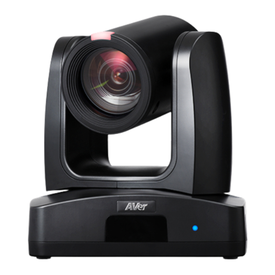
Page 9: Product Introduction
Product Introduction Overview (1) Tally Lamp (6) PoE+ IEEE 802.3AT (10) Audio In** (2) IR Sensor (7) RS-232 Port (11) HDMI Port (3) LED Indicator (8) RS-422 Port (12) 3G-SDI*** (4) Light Sensor* (9) USB 3.0 Port (Type-B) (13) DC Power Jack (5) Kensington Lock * The model names with “I”... -
Page 10: Pan And Tilt Angle
Pan and Tilt Angle 90° 170° 170° 30°... -
Page 11: Dimensions
Dimensions 80mm 156.5mm 145mm 180mm 161.3mm 145mm 156.5mm 161.3mm 180mm... - Page 12 Ceiling Mount 80mm 104mm 153mm 161.3mm 180mm 200.8mm...
- Page 13 Wall Mount 180mm 161.3mm 206mm 263.2mm...
-
Page 14: Device Connection
Device Connection Joystick (Camera control) Laptop (Management/Presentation) Microphone Audio input RS-232 RS-422 3G-SDI Monitor/TV PoE+ (Display) Lecture capture system HDMI (Record) Professional PTZ Camera Web application (Remote Management) PoE Connection Connect the camera to the router or switch through the PoE+ port. [Note] Only support IEEE 802.3AT PoE+ standard. -
Page 15: Rs-232 And Rs-422 Connection
RS-232 and RS-422 Connection Connect through the RS-232 or RS-422 for camera control. RS-232 RS-232 (VISCA) cable (Not included) Joystick Laptop... - Page 16 ● RS-232 Port Pin Definition Mini DIN9 Function I/O Type Signal Description PIN # Output Data Terminal Ready Input Data Set Ready VISCA IN Output Transmit Data Input Receiver Data Output Data Terminal Ready Input Data Set Ready VISCA OUT Output Transmit Data Input...
- Page 17 ● RS-232 mini DIN9 to mini DIN8 Cable Pin Definition Mini DIN8 Cable Pin Definition Signal...
- Page 18 ● Din8 to D-Sub9 Cable Pin Definition...
- Page 19 RS-422 RS-422 cable (Not included) Joystick Laptop [Note] Use cat5e splitter for multi-camera connection. RS-422 Pin Cat5e splitter pin assignment: Camera Camera/Joystick Camera/Joystick...
-
Page 20: Audio Input Connection
Audio Input Connection Connect the audio device for audio receiving. [Note] Line input level: 1Vrms (max.). Mic input level: 50mVrms (max.); Supplied voltage: 2.5V. Microphone Audio Mixer... -
Page 21: Video Output Connection
Video Output Connection HDMI Use the HDMI cable to connect with monitor or TV for video output. HDMI Cable Monitor/TV 3G-SDI Connect to 3G-SDI monitor for video output. 3G-SDI Cable (Not Included) SDI Monitor [Notes] HDMI and 3G-SDI monitors can be connected to camera and output live video simultaneously; ... - Page 22 Cable Fixing Plate Installation Secure the cable fixing plate to the camera with 3 M2 x 4mm screws (included in the package). Use 4 cable ties to secure the cables and cable Plug in cables. fixing plate.
- Page 23 Ceiling Mount Installation 1. Secure the mount bracket on the ceiling. 2. Install the mount bracket on the camera. Screw: 4 screws, M4 x 10mm (Not Screw: 2 screws, 1/4"-20 L=6.5mm (Included Included in the package) in the package) 3. Slide the mount bracket with the camera 4.
-
Page 24: Camera Installation
Camera Installation Angle A: less than 30˚ Height B: 2~3m from floor Distance C: longer than 3m away from podium Position: center of classroom Distance between the camera and the target (presenter): Optical zoom ratio ability Upper body size Full body size 3~16m... -
Page 25: Remote Control
Remote Control (10) (12) (11) (14) (13) (15) (17) (16) (18) (19) Name Function Turn the unit on/standby. (1) Power Open and exit the OSD menu. (2) Menu CAM1 to CAM3 button (3) Camera Select Select a camera to operate. ... - Page 26 Name Function Reset the Pan-Tilt position. ( 11) PT Reset Left and right orientation setting. (12) L/R SET Press “L/R SET” + “1” button to reset setting. Press “L/R SET” + “2” button to move to opposite direction. Zoom in/out slowly. (13) Zoom Slow +/- Enable manual focus.
-
Page 27: Set Up The Camera
Set Up the Camera OSD Menu You can use the supplied Remote Control to operate the OSD Menu. Press the button to call out the OSD menu and use the ▲ , ▼ , , and buttons to operate the OSD menu. IP Address Setup Static IP 1. -
Page 28: Dhcp
DHCP 1. Press the button on the remote control to call out the OSD menu. 2. Go to Network > DHCP > On. 3. After turning the DHCP on, the user can go to System > Information to view the IP address. -
Page 29: Osd Menu Tree
OSD Menu Tree Camera Set up camera parameters – Exposure Mode, White Balance, Pan Tilt Zoom, Noise Reduction, Saturation, Contrast, Sharpness, Mirror and Flip. Layer Layer Layer Layer Layer Full Auto Exposure Value -4/-3/-2/-1/0/1/2/3/4 Gain Limit Level 24dB/27dB/30dB/33dB/36dB /39dB/42dB Slow Shutter Off/On Shutter Priority Exposure Value... - Page 30 Layer Layer Layer Layer Layer 50Hz: 1/1, 1/2, 1/3, 1/6, 1/12, 1/25, 1/50, 1/75, 1/100,1/120,1/150,1/215, 1/300, 1/425, 1/600, 1/1000, 1/1250, 1/1750, 1/2500, 1/3500, 1/6000, 1/10000 Iris Level F1.6 /F2.0/F2.4/F2.8/ F3.4/F4.0/F4.8/F5.6/F6.8/ F8.0/F9.6/F11/F14/Close Gain Level 0 dB/3 dB/6 dB/9 dB/12 dB /15 dB/18 dB/21 dB/24dB/ 27dB/30dB/33dB/36dB/39dB /42dB Bright...
-
Page 31: Video Output
Video Output Select video resolution (2160p is only supported on certain models). Layer Layer Layer Video Output Theme Mode Standard ZOOM TEAMS NDI HX3 Frequency 50 Hz/59.94 Hz/60 Hz Resolution 2160P/60, 2160P/59, 2160P/50, 2160P/30, 2160P/29, 2160P/25, 1080P/60, 1080P/59, 1080P/50, 1080P/30, 1080P/29, 1080P/25, 1080I/60, 1080I/59, 1080I/50, 720P/60, 720P/59, 720P/50, Network Set up IP mode –... -
Page 32: System
System Status OSD: Enable/disable Preset status (Save Preset, Call Preset, Cancel Preset) display on the screen. Camera Selector: Set the camera ID 1~3 for using remote control on multiple cameras control (also see No.3 Camera Select in Remote Control chapter). ... -
Page 33: Web Setup
Connect the camera from a remote site through the internet. Recommended browser: Chrome. Access the Web Interface of the Camera To access the Web interface of the camera, you have to find the IP address of the camera using AVer IPCam Utility or AVer PTZ Management software. - Page 34 To access the Web interface, double-click on the IP address in the IPv4 Address column. For the first-time user, you will be prompted with a Login window to change the ID and password. 4. Login with the new ID/Password, the Web interface of the camera will be displayed. Please refer to the Live View chapter for more details.
-
Page 35: Accessing The Camera Via Aver Ptz Management
Accessing the Camera via AVer PTZ Management To find the IP address of your cameras using the AVer PTZ Management, follow the steps below. 1. Download the AVer PTZ Management software from https://www.aver.com/download-center 2. Download the Windows program and install it. -
Page 36: Live View
Live View You can control the camera and operate the Preset functions using this page. Camera Control Click the Camera Control tab to display the panel below for operation. Pan-Tilt-Zoom Control to navigate the camera view. Adjust the Pan Speed and Tilt Speed if , and necessary. -
Page 37: Preset
Focus Auto Focus : Click for the camera to perform the auto focus. Manual Focus : Click to manually adjust the focus. You can use the Focus + and Focus – buttons to adjust the focus. One Push Focus : Click to automatically adjust the focus once. Focus Near Limit: Set up the focus distance limit. - Page 38 To perform the go to preset positions: 1. Input a preset number (0~255) in the Load Preset column or click a preset number (0~19) in the Quick Call section. 2. Click Load, the camera will move to the preset position. When operating the go to preset positions, you can optionally adjust the Preset Speed, enable/disable the Video Freeze while Preset or Preset Accuracy function.
-
Page 39: Camera Settings
Camera Settings Exposure Click the Exposure tab to display the panel below for configuration. Exposure Mode: Options include Full Auto, Iris Priority, Shutter Priority, Bright, and Manual. Select an exposure mode and optionally adjust the value of Exposure Value, Gain Level, Shutter Speed, Gain Limit Level, Iris Level, and BLC. -
Page 40: Image Process
Image Process Click the Image Process tab to display the panel below for configuration. White Balance: Options include AWB, ATW, Indoor, Outdoor, One Push and Manual. If Manual is selected, adjust the R Gain and B Gain manually. If One Push is selected, click the Set button in the One Push field when placing a white paper sheet in front of the camera lens. -
Page 41: Video & Audio
Video & Audio You can configure video and audio settings on this page. Video Setting: Power Frequency: Select 50Hz, 59.94Hz or 60Hz based on your region. Video Output Resolution: Select a resolution to display on your video output device. ... - Page 42 Audio Setting: Audio Input Type: Select an audio source for the audio input. Line In or MIC In. Encoding Type: Select AAC. Audio Volume: Adjust the audio volume. USB Audio Enable: Select On or Off.
-
Page 43: Network
Static IP: Select Off to disable the DHCP button and manually input the IP Address, Netmask, Gateway and DNS. Click Confirm to save the settings. Hostname: The default Hostname is AVer. You can change the hostname to be displayed on other devices, e.g. IP router. - Page 44 Example 1 vMix: Set the workstation and the TR300V2 camera in the same network. Check the workstation’s IP address (Destination IP). Example: Select SRT (Listener) from Stream Type in vMix Input Select window. Enter the information into the SRT Settings TR300V2 web interface, then click on Start Stream, Connect Status shows Connected.
- Page 45 Example2 OBS (Open Broadcaster Software): Set the workstation and the TR300V2 camera in the same network. Check the workstation’s IP address (Destination IP). Example: Open OBS, add a scene, add a source, enter srt://Work Station IP:port?mode=listener Example: srt://10.100.105.127:8889?mode=listener [Note] If there is no image, please try right-click on the source->Transform->Fit to screen to re-scale image.
-
Page 46: Advanced Setting
Advanced Setting SmartShoot Setup the block area for the camera to detect object and follow-up the object to move the camera when the object is in block area that user has set. 1. In the advanced setting interface, select the “Number of block” (2, 3, or 4). Each block is corresponding to one preset position. - Page 47 2. Set the preset positions in order (Preset 6 to Preset 9). Use direction control panel to move the camera to wanted position and select “save” to save the preset position. And, a snapshot of the preset image will show at corresponding image display box. Repeat the step to set another preset position.
-
Page 48: Smartframe
SmartFrame Press button on the remote control to enable to auto focus the face of object and zoom in. Select “Enable” to activate the function. [Note] Only certain models support SmartFrame. Debug Information Select ”Enable”, and the human detection within the green rectangle will show on the HDMI output. -
Page 49: Ndi
Encoding Type: Select H.264 or H.265. Local Device Name: Enter a name of the camera to be shown within NDI devices. For best results, name all AVer cameras the same Local Device Name. e.g. PTZ Cameras or Tracking Cameras. - Page 50 Receive Group: Enter a name of the receive group. The Receive Group allows you to limit which users on your LAN can see the NDI source. For best results, the Receive Group should remain Public. Once the Receive Group is changed, you will need to join the Receive Group through NDI®...
-
Page 51: System
You can view the system information, or configure some system settings on this page. Upgrade firmware: Follow below steps to upgrade the firmware. Download the newest firmware from https://www.aver.com/download-center/ On the Web page, go to System > Upgrade firmware. Click Choose File to select the firmware. - Page 52 You can select Off to disable the sleep mode. To perform this function, ensure to select ZOOM in the Video & Audio > Theme Mode setup field. Help Improving AVer Camera: Select the function to send anonymous usage data for Aver Information Inc.
-
Page 53: Appendix
Appendix VISCA RS-232 Command Table... -
Page 55: Visca Over Ip Settings
Visca over IP Settings... -
Page 56: Cgi Command
CGI Command...
Need help?
Do you have a question about the PTZ310V2 and is the answer not in the manual?
Questions and answers