Table of Contents
Advertisement
Quick Links
Advertisement
Table of Contents

Subscribe to Our Youtube Channel
Related Manuals for HiBoost F27K-6S-IoT


Summary of Contents for HiBoost F27K-6S-IoT
- Page 1 l'/BOOST �� Boost Your Bars User Manual F27K-6 S-IoT Mobile Signal Booster...
-
Page 2: Table Of Contents
--.1/BOOST �� TABLE OF CONTENT T A BL E OF CON T EN T S · ·· ·· ·· ·· ·· · ·· ·· ·· ·· ·· · · · ·· ·· ·· ·· ·· · · · ·· ·· ·· ·· ·· · ···· ·· ·· ·· ···· · ·· ·· ·· ·· ·· · · · ·· ·· ·· ·· ·· · · · ·· ·· 2 OPER A T I ON ··... -
Page 3: Operation
The F27K-6S-IoT industrial amplifier requires outside and inside antennas connected with appropriate coaxial cables and a splitter network. The F27K-6S-IoT can typically power 8-15 indoor antennas but the exact number of antennas, length of cable or other accessories needed can vary according to the size and construction of materials used in the building, outdoor signal strength and layout of the structure. - Page 4 --.1/BOOST �� Multiple Antenna Installation Sample 1.Outdoor Wide Band Directional Antenna 2. Booster 3. Indoor Wide Band Panel Antenna 4.Coupler 5. Splitter 6. Indoor Wide Band Dome Antenna Optional Accessories Recommended Outdoor Wide Band Outdoor Wide Band RF Cables Directional Antenna Panel Antenna ..
-
Page 5: Key Features
Cavity Splitter (2,3,4 way) Wilkinson Splitter (2,3,4 way) KEY FEATURES • Self-adaptive Smart Level Control (ALC): Enables convenient 'plug and play' installation and optimum coverage in complex and dynamically changing RF signal environments. • ISO: Smart isolation gain processing to avoid self-oscillation between antennas and avoid interference to the carrier network. -
Page 6: H Ow To Find The Location With The Strongest Received Signa
--.1/BOOST �� Phillips Screwdriver Drill Mobile Phone Name Specification Quantity Remark <PB Plastic Expansion Bolt Standard accessories M6*50 Tapping Screws Standard accessories Electric Drill Drill Bit Before you get started, you will need to plan the layout of your system. This involves finding the location with the strongest received signal from the cellular tower, as well as antenna, booster, and cable placement. - Page 7 on the best signal for installation. • LCD Display Method Connect the outdoor antenna to the booster's outdoor port. Fix the outdoor antenna on the roof of the building and point it to the nearest cell tower. Then have a look at the gain and output power value displayed on the amplifier's LCD.
-
Page 8: Install Outdoor Antenna
�� --.1/BOOST signal bars. For more details refer to https://www.hiboost.com/blog/ Please try to receive a signal from cell towers that are not overloaded with Note: multiple users. This can be estimated by the population density in the area served by the tower. For example, it is recommended to avoid cell towers near supermarkets, shopping malls, stadiums or any other public places visited by many people regularly. -
Page 9: Install Indoor Antenna
• 1 to2 inch diameter pole U-bolt Outdoor wide b and panel antenna installation for reference Note: Be sure the cradle is at the desired height and rotated toward the strongest cellular signal before tightening the nuts. Do not over tighten. Wrap waterproof tape around the connectors between outdoor antenna and feeder line to avoid moisture ingress. -
Page 10: Install The Signal Booster
--.1/BOOST �� When choosing an indoor wide band dome antenna, the best place to install it is in the center of area that needs signal improvement. Install the dome antenna as shown on the figure below: Indoor wide band dome antenna installation for reference 1.6 Install the signal booster The signal booster should be mounted in an easily accessible area so it's easy to perform general maintenance. -
Page 11: Power Up Your Signal Booster
As you route and pull cabling, follow these general guidelines: • Bend cables and route them smoothly, and protect the outer skin against any damage. • Keep horizontal cables straight and fasten them with a tie every three to five feet. -
Page 12: Signal Booster Status
--.1/BOOST �� Cellular phones will operate just fine if they are showing 1-2 bars. Some phones by different manufactures will often show widely different signal level results. Also, phones by the same manufacture can show different results if they have different software versions. - Page 13 Band: Shows the working frequency bands where the booster is operating. UL/DL: Shows real-time uplink and downlink gain(dB). These values will change slightly as the ALC or ISO makes changes to the gain to optimize coverage. Power: Shows real-time downlink power(dBm) that the booster is delivering to the indoor antenna port.
-
Page 14: Port Description
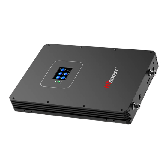
--.1/BOOST �� Port description 1-LED Light, 2-LCD, 3-Outdoor Antenna Port, 4-Ethernet Port, 5-Indoor Antenna Port, 6- Power Port, 7-SIM Card Slot, 8-Debug Port, 9-Antenna Port) 14/23... -
Page 15: L Cd S Tat U S
"OSC" Status:OSC status indicates if the booster has enough isolation between outdoor and indoor antennas to avoid loop back or so-called self-oscillation. Thanks to a very smart isolation gain processing, this amplifier is fully protected from creating interference with the carrier's local cell site networks. "OSC" showing on the LCD display means that the ISO function is doing its job and the self-oscillation has been eliminated. -
Page 16: L Ed S Tat U
--.1/BOOST �� mandatory, since the self-adaptive ALC system and isolation gain processing automatically solve most problems. LED Status Status Normal, no network connected Net LED Connecting to network Green Active connection to Green flashing management server When the Alarm led indicators are flashing, please check the ISO and Alarm LED colors. -
Page 17: C Ontrol Bu Ttons O Peration And Man U Al Gain Control (M G
When any band shows OSC status with a yellow background, and the output power is less than the rated max output value, consider the donor antenna and service antenna isolation. The best performance is all bands show a blue circle, and the Alarm LED is solid, or slowly flashing. -
Page 18: Network Status
--.1/BOOST �� • Choose one band which need reduce the gain value. • Click the MGC ,it will show currently working Gain and MGC value • Enter the MGC,the gain will reduce by 1 dB, Press " +" once shortly and the gain value will be reduced by 1dB. -
Page 19: T Rou B L Es H Oo T In
TROUBLESHOOTING Problem Solution The signal booster has no power. Check that the AC outlet is working. Check all the connections between the The booster's power is on but the different components of the system. phone is not connected to the Change the direction of the outdoor donor network and still cannot antenna or its installed position. -
Page 20: Fcc Rf Exposure State M En
--.1/BOOST �� 1. Adjust the antennas' directions or locations to lower downlink received signal level. 2. Slowly reduce the downlink gain using the Manual Gain Controls. 3. If the above methods don't work, reduce the booster's gain with an external attenuator in line with the outdoor antenna or replace with lower gain antenna. -
Page 21: Ic Rf Exposure Statement
IC RF EXPOSURE STATEMENT This device is in compliance with RF exposure limits. The minimum distance from your body to the antennas used with this device should be 20 CM. Le present appareil est conforme aux conformite ou aux limites d'intensite de champ RF. -
Page 22: Specifications
--.1/BOOST �� WARNING. T his is NOT a CONSUMER device.It is designed for installation by FCC LICENSEES and QUALIFIED INSTALLERS . You MUST have an FCC LICENSE or express consent of an FCC Licensee to operate this device. U nauthorized use may result in significant forfeiture penalties.including penalties in excess of $100,000 for each continuing violation. -
Page 23: Produc T W A Rr A N
Returned Material Authorization (RMA) number supplied by HiBoost. Hi Boost will supply two options, repair or replace. HiBoost will cover the cost of delivery for the consumers located within the continenta l U.S.
Need help?
Do you have a question about the F27K-6S-IoT and is the answer not in the manual?
Questions and answers