Table of Contents
Advertisement
Advertisement
Table of Contents

Related Manuals for HiBoost F10G-5S-LCD


Summary of Contents for HiBoost F10G-5S-LCD
- Page 1 User's Manual F10G-5S-LCD 1 / 20 BOOST CELL PHONE SIGNAL BOOSTERS MADE BY HUAPTEC...
-
Page 2: Table Of Contents
Table of contents WHAT IS INCLUDED .................. 3 HOW IT WORKS ................. 3 TOOL REQUIRED ................3 HOW TO INSTALL YOUR NEW CELLULAR BOOSTER ......4 3.1 Overview ................... 4 3.2 Plan the layout of your system ..........6 3.3 Check for Signal Strength ............6 3.4 Run coaxial cable ............... -
Page 3: What Is Included
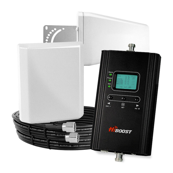
WHAT IS INCLUDED 1. Booster F10G-5S-LCD 2. Outdoor Yagi 9dbi Antenna & 50’5D Coaxial Cable 3. Indoor Panel 7dbi Antenna& 50’5D Coaxial Cable 4. AC/DC Power Adapter 1 HOW IT WORKS The cellular booster provides reliable two-way cellular coverage by improving signal strength in homes, buildings, offices, and other areas where cellular reception is weak or unreliable. -
Page 4: Overview
3 HOW TO INSTALL YOUR NEW CELLULAR BOOSTER 3.1 Overview This guide will help you properly install your cellular booster kit. It is important to read through all of the installation steps before installing your equipment. Thoroughly read through the instructions, visualize where all the equipment will need to be installed and do a soft installation before mounting any equipment. -
Page 5: Plan The Layout Of Your System
3.2 Plan the layout of your system Before you get started you will need to plan the layout of your system. This involves checking signal strength for signals coming from the cellular tower, as well as antenna, booster and cable placement. 3.3 Check for Signal Strength Select a location on the roof of the building to install the signal antenna, by monitoring your cellular phone’s signal strength (signal bars) to find the strongest... -
Page 6: Install The Server (Indoor) Antenna
3.6 Install the Server (Indoor) antenna Connect one end of the coaxial cable to the antenna and the other end to the cellular booster where it is marked “Indoor”. Select the installation location of your supplied server (outdoor) antenna based on the following: Omni Ceiling directional antenna Place in the center of the area where the signal needs to be amplified. -
Page 7: Understand The Ports, Lcd And Led Status,Mgc
unusable signal quality can cause oscillation, this is why it is important to fully understand the LCD indications on your booster, as they will help you identify and solve any potential issues. The LCD indicates the status of the booster system. 4 UNDERSTAND THE PORTS, LCD and LED STATUS,MGC 4.1 Repeater ports 1) Outdoor port: connected with the donor antenna by cable. - Page 8 coverage. “Power dBm”– Power Indication. The displayed value shows real-time downlink power that the amplifier is delivering to the indoor antenna port. When the amplifier DL output power is lower than -10dBm, the value will display ”---”. “ISO” – Isolation Alarm Indication. When the system does not have enough isolation between the outdoor and indoor antennas, the “ISO”...
-
Page 9: Led Status
4.3 LED Status 1. Status and definition of Power indicator: Status Definition Green Normal DC power problem 2. Status and Definition of Alarm indicator; Alarm LED only works for downlink signals Status Meaning Solve methods Check coverage, leave as is if it's good; if Output power is not maximum. -
Page 10: Manual Gain Control Operation
Not working properly. Check coverage. Leave it as is if it’s Deep loop back or self-oscillation Quick Flashing Green good. Actions must be taken if coverage is not good. Severe loop back or self- oscillation Quick Flashing Red Not working properly, actions must be The booster automatically shuts off taken. -
Page 11: Manual Gain Control (Mgc)
When the LCD is in the alarm display mode, press the “SET” key and the LCD screen will display the alarm indication showing the affected band. Pressing the “INC+” (or “ DEC-“) key and the LCD will switch to help tips. If none of keys are depressed within 30 seconds, the display will return to the fixed display mode. -
Page 12: Understand The Antenna
5 UNDERSTAND THE ANTENNA 5.1 Donor (Outdoor) antenna The Yagi Lpda Antenna The yagi is a very precise directional antenna with a powerful reach. This antenna should be installed in an elevated position and must be pointed towards your carrier’s cellular tower. NOTE:This antenna is not meant to capture signal from multiple carriers. - Page 13 Outdoor Antenna & Cable Kit Options 2.Kit 11-100400 Yagi 11dbi Antennac& 100' 400 Coaxial Cable 3. Kit 11-7550 Yagi 11dbi Antenna & 75' 5D Coaxial Cable 4. Kit 11-100500 Yagi 11dbi Antenna & 100' 5D Coaxial Cable Kit 10-3050 Panel 10dbi Antenna & 30' 5D Coaxial Cable Kit 10-50400 Panel 10dbi Antenna &...
- Page 14 23. Kit 7-10050 Panel 7dbi Antenna & 100' 5D Coaxial Cable 24. Kit 5-30400 Omni 5dbi Antenna & 30' 400 Coaxial Cable 25. Kit 5-3050 Omni 5dbi Antenna & 30' 5D Coaxial Cable 26. Kit 5-50400 Omni 5dbi Antenna & 50' 400 Coaxial Cable 27.
-
Page 15: Troubleshooting
14. Kit 3-50400 Omni 3dBi Antenna & 50' 400 Coaxial Cable 15. Kit 3-75400 Omni 3dBi Antenna & 75' 400 Coaxial Cable 16. Kit 3-100400 Omni 3dBi Antenna & 100' 400 Coaxial Cable 17. Kit 32-50400-50 2 Omni 3dBi Antenna & 50' 400 Coaxial Cable & a 50 Ohm 2-Way Splitter 18. -
Page 16: Frequently Asked Questions
them. The signals travel like rays of sunlight, a directional antenna will send the signal in the direction that it is pointing. An omni directional antenna will send the signal in every direction around it. So depending on your equipment it’s important to be sure that your Indoor antenna is not sending the signal back into the outdoor antenna. -
Page 17: Warning And Statement
9 Warning and Statement Note:This equipment has been tested and found to comply with the limits for a Class B digital device, pursuant to Part 15 of the FCC Rules. These limits are designed to provide reasonable protection against harmful interference in a residential installation. -
Page 18: Specification
10 Specification F10G-5S-LCD RF Parameter Uplink Downlink 700MHz Lower(A+B+C) 698~716MHz 728~746MHz 700MHz Upper C 776~787MHz 746~757MHz Frequency Cell800 824~849MHz 869~894MHz Range PCS1900 1850~1915MHz 1930~1995MHz AWS2100 1710~1755MHz 2110~2155MHz 700MHz Lower(A+B+C) 18MHz 700MHz Upper C 11MHz Band width Cell800 25MHz PCS1900 65MHz...
Need help?
Do you have a question about the F10G-5S-LCD and is the answer not in the manual?
Questions and answers