Table of Contents
Advertisement
Quick Links
Advertisement
Table of Contents

Related Manuals for HiBoost F15G-CP


Summary of Contents for HiBoost F15G-CP
- Page 1 Consumer signal booster user manual ...
-
Page 2: Table Of Contents
Content What is included ................4 HOW IT WORKS .................. 4 TOOL REQUIRED .................. 4 HOW TO INSTALL YOUR NEW CELLULAR BOOSTER ...... 5 Overview .................. 5 Plan the layout of your system ............ 7 Check for Signal Strength ............. 7 Run coaxial cable................ 8 Install the Donor (Outdoor) antenna ........... 9 ... - Page 3 Antenna Kitting Options .... Error! Bookmark not defined. TROUBLESHOOTING ................ 15 FREQUENTLY ASKED QUESTIONS ............ 19 FCC RF Exposure Statement ............... 20 Warning .................... 21 Specification .................. 21 ...
-
Page 4: What Is Included
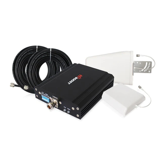
WHAT IS INCLUDED 1. Booster F15G‐CP 2. Outdoor Yagi 9dbi Antenna & 30' SIG5D Coaxial Cable 3. Indoor Panel 10dbi Antenna & 3' SIG5D Coaxial Cable 4. AC/DC Power Adapter 1 HOW IT WORKS The cellular booster provides reliable two‐way cellular coverage by improving signal strength in homes, buildings, offices, and other areas where cellular reception is weak or unreliable. The system amplifies the signal from the nearest cellular tower and retransmits at a higher power level within a local area. ... -
Page 5: How To Install Your New Cellular Booster
3 HOW TO INSTALL YOUR NEW CELLULAR BOOSTER 3.1 Overview This guide will help you properly install your cellular booster kit. It is important to read through all of the installation steps before installing your equipment. Thoroughly read through the instructions, visualize where ... - Page 6 • BOOSTER – select location •Install the booster in an area that is protected from the weather, properly ventilated and is away from excessive heat and moisture. • DONOR ANTENNA (OUTDOOR)‐ select location •Mount the signal (outdoor) antenna in an elevated outdoor location so that it points towards the cellular tower and away from where the inside antenna will be located. • OUTDOOR COAXIAL CABLE ‐ select location •The outdoor coaxial cable is used to connect the donor (outdoor) antenna to the booster. • INDOOR COAXIAL CABLE‐ (if used) •The indoor coaxial cable is used to connect the server (indoor) antenna to the booster. • SERVER ANTENNA (indoor) •The ideal location for the distribution antenna will be the area of your property where you need to improve the signal most. •NOTE:The signal strength will be strongest closest to the antenna. •IMPORTANT: The signal antenna (outdoor)should always be separated from the distribution antenna (indoor)by at least 20 vertical feet including the separation of a thick barrier such as a roof or a wall. Depending on the strength of your outdoor ! signal, the weaker the signal the less separation distance is required. •LIGHTNING SURGE PROTECTOR‐ (SOLD SEPARATELY) •The lightning surge protector connects in between the signal antenna and the booster. •IMPORTANT: Lightning surge protector must be grounded. • COMMISSIONING THE SYSTEM...
-
Page 7: Plan The Layout Of Your System
3.2 Plan the layout of your system Before you get started you will need to plan the layout of your system. This involves checking signal strength for signals coming from the cellular tower, as well as antenna, booster and cable placement. 3.3 Check for Signal Strength Select a location on the roof of the building to install the signal antenna, by monitoring your cellular phone’s signal strength (signal bars) to find the strongest signal from your carrier’s cellular tower. Mark that area as the installation location for the Donor (outdoor) IMPORTANT: Confirm that you have at least 20 feet of vertical distance between the marked antenna location and the location where you will place the Server (indoor) antenna. To prevent the system from oscillation ... -
Page 8: Run Coaxial Cable
(feedback) you want to ensure that there is enough separation between the distribution and signal antenna or that they are shielded from each other to ensure the distribution antenna does not send a signal back into the signal antenna. If you cannot achieve these separations, either choose an alternate location for the donor (outdoor) antenna or determine if there are natural barriers in the building construction itself that will attenuate signals between the two antennas so that oscillation can be prevented. 3.4 Run coaxial cable Loosely run the coaxial cable from your outdoor antenna to your booster. (After you have tested the system you can permanently secure the coaxial cable). ... -
Page 9: Install The Donor (Outdoor) Antenna
center pins on the connectors. 3.5 Install the Donor (Outdoor) antenna Connect the supplied coaxial cable to the antenna. We recommend applying silicone caulking to fully waterproof the connection. Attach the cable in such a way that a drip loop is formed. Once mounted, connect one end of the coaxial cable to the donor (outdoor) antenna and the other end to the cellular booster where it is marked “outdoor” 3.6 Install the Server (Indoor) antenna Connect one end of the coaxial cable to the antenna and the other end to the cellular booster where it is marked “indoor”. Select the installation location of your supplied server (outdoor) antenna based on the following: ... -
Page 10: Install Your Cellular Booster
Omni Ceiling directional antenna Place in the center of the area where the signal needs to be amplified. Panel directional antenna Place in the outer perimeter of the area the signal needs to be amplified. Whip Omni directional antenna Mount directly to the connector marked “indoor” on the cellular booster. 3.7 Install your cellular booster Install the cellular booster in a location that is properly ventilated and not exposed to excessive heat, moisture and/or direct sunlight. The optimal area would be on a wall located near a power outlet. It should be mounted in an easily accessible area so it’s easy to perform general maintenance with the coaxial cable connections, dip switch settings and power adaptor. ... -
Page 11: Check The Cellular Booster Status
indoor and outdoor antennas. 2. Never point the front of the donor (outdoor) antenna towards the inside of the server (outdoor) antenna. 3. Verify that the supplied coaxial cables from both the donor (outdoor) antenna and the server (outdoor) antenna are properly connected to the cellular booster before powering it up. 4. Carefully plug in the supplied power adaptor into the back of the cellular booster where it is marked ‘power’ and connect the other end to a power outlet. The LED indicator marked power should light up green. 3.9 Check the Cellular Booster Status Your cellular booster comes equipped with electronic sensors designed to identify cellular signal overload or oscillation which can hinder signal boosting ... -
Page 12: Repeater Ports
4 UNDERSTAND THE PORTS, MGC DIP SWITCH, LED STATUS 4.1 Repeater ports 1) Outdoor port: connected with the donor antenna by cable. 2) Indoor port: connected with server antenna directly or by cable. 3) DC IN: connected with power supply. 4.2 Manual gain control (MGC) Switches represent Downlink... -
Page 13: Led Status
Att. Att. 0 dB 11dB 22dB 1 dB 12dB 23dB 2 dB 13dB 24dB 3 dB 14dB 25dB 4 dB 15dB 26dB 5 dB 16dB 27dB 6 dB 17dB 28dB 7 dB 18dB 29dB 8 dB 19dB 30dB 9 dB 20dB 31dB 10 dB... -
Page 14: Understand The Antenna
5 UNDERSTAND THE ANTENNA 5.1 Donor (Outdoor) antenna The Yagi Lpda Antenna The yagi is a very precise directional antenna with a powerful reach. This antenna should be installed in an elevated position and must be pointed towards your carrier’s cellular tower. NOTE:This antenna is not meant to capture signal from multiple carriers. The Panel Antenna The panel is a directional antenna with a 120 degree reach and is designed to capture the signal from multiple carrier towers. This antenna should be installed in an elevated position and must be pointed towards your carrier’s cellular towers. Yagi Antenna The yagi is a very precise directional antenna with a powerful reach. This antenna should be installed in an elevated position and must be pointed towards your carrier’s cellular tower. NOTE: This antenna can only support single band signal booster. 5.2 Server (Indoor) antenna The Whip Antenna The whip antenna is an omni‐directional antenna with a 360 degree reach. It is designed to distribute the signal from the center of the affected area. Typically it is connected directly to the booster. The Omni Antenna The omni antenna is an omni‐directional antenna with a 360 degree reach. It is designed to distribute the signal from the center of the affected area. Typically it is installed in a false or dropped ceiling. The Panel Antenna The panel is a directional antenna with a 120 degree reach and is designed to distribute the signal from a perimeter wall or ceiling. ... -
Page 15: Antenna Kitting Options
5.1 Antenna Kitting Options Outdoor Antenna & Cable Kit Options Kit 11‐3050 Outdoor Yagi 11dbi Antenna & 30’ 5D Coaxial Cable Kit 11‐50400 Outdoor Yagi 11dbi Antenna & 50’ 400 Coaxial Cable Kit 11‐5050 Outdoor Yagi 11dbi Antenna & 50’ 5D Coaxial Cable Kit 11‐75400 Outdoor Yagi 11dbi Antenna & 75’ 400 Coaxial Cable Kit 11‐100400 Outdoor Yagi 11dbi Antenna & 100’ 400 Coaxial Cable Kit 11‐7550 Outdoor Yagi 11dbi Antenna & 11’ 75 Coaxial Cable Kit 11‐10050 Outdoor Yagi 11dbi Antenna & 100’ 50 Coaxial Cable Kit 10‐30400 Outdoor Panel 10dbi Antenna & 30’ 400 Coaxial Cable Kit 10‐3050 Outdoor Panel 10dbi Antenna & 30’ 5D Coaxial Cable 10. Kit 10‐50400 Outdoor Panel 10dbi Antenna & 50’ 400 Coaxial Cable 11. Kit 10‐5050 Outdoor Panel 10dbi Antenna & 50’ 5D Coaxial Cable 12. Kit 10‐75400 Outdoor Panel 10dbi Antenna & 75’ 400 Coaxial Cable 13. Kit 10‐100400 Outdoor Panel 10dbi Antenna & 100’ 400 Coaxial Cable 14. Kit 10‐7550 Outdoor Panel 10dbi Antenna & 75’ 5D Coaxial Cable 15. Kit 10‐10050 Outdoor Panel 10dbi Antenna & 100’ 5D Coaxial Cable 16. Kit 9‐30400 Outdoor Yagi 9dbi Antenna & 30’ 400 Coaxial Cable ... - Page 16 27. Kit 5‐5050 Outdoor Omni 5dbi Antenna & 50’ 5D Coaxial Cable 28. Kit 5‐70400 Outdoor Omni 5dbi Antenna & 70’ 400 Coaxial Cable 29. Kit 5‐100400 Outdoor Omni 5dbi Antenna & 100’ 400 Coaxial Cable 30. Kit 5‐7550 Outdoor Omni 5dbi Antenna & 75’ 50 Coaxial Cable 31. Kit 5‐10050 Outdoor Omni 5dbi Antenna & 100’ 5D Coaxial Cable Indoor Antenna & Cable Kit Options Kit 5‐0 Indoor Whip 5dbi Antenna Kit 100‐1550 Indoor Panel 10dbi Antenna & 15' 5D Coaxial Cable Kit 100‐30400 Indoor Panel 10dbi Antenna & 30’ 400 Coaxial Cable Kit 100‐5050 Indoor Panel 10dbi Antenna & 50’ 5D Coaxial Cable Kit 100‐7550 Indoor Panel 10dbi Antenna & 75’ 5D Coaxial Cable Kit 102‐7550‐50 2 Indoor Panel 10dbi Antennas & 75’ 5D Coaxial Cable & a 50 Ohm 2‐ways Splitter Kit 103‐7550‐75 3 Indoor Panel 10dbi Antennas & 75’ 5D Coaxial Cable & a 75 Ohm 3‐ways Splitter Kit 104‐7550‐50 4 Indoor Panel 10dbi Antennas & 75’ 5D Coaxial Cable & three 50 Ohm 2‐ways Splitters Kit 100‐10050 Indoor Panel 10dbi Antenna & 100’ 5D Coaxial Cable 10. Kit 100‐30400 Indoor Panel 10dbi Antenna & 100’ 400 Coaxial Cable 11. Kit 100‐50400 Indoor Panel 10dbi Antenna & 50’ 400 Coaxial Cable ...
-
Page 17: Troubleshooting
23. Kit 32‐50400‐50 2 Indoor Omni 3dbi Antennas & 50’ 400 Coaxial Cable & a 50 Ohm 2‐ways Splitter 24. Kit 33‐50400‐75 3 Indoor Omni 3dbi Antennas & 50’ 400 Coaxial Cable & a 75 Ohm 3‐ways Splitter 25. Kit 34‐50400‐50 4 Indoor Omni 3dbi Antennas & 50’ 400 Coaxial Cable & three 50 Ohm 2‐ways Splitters 6 TROUBLESHOOTING The LED alarm lights represent the status of the booster on each frequency. When the lights are green the device is operating normally meaning that it is not experiencing any oscillation (feedback) and it is boosting ... - Page 18 IMPORTANT NOTES The 2 most important things to look for when setting up your system is: A good input signal (the best you can find) Isolating the outdoor (donor) antenna from the indoor (server) antennas so they do not feedback into each other. By capturing the best input signal you will be able to enjoy the maximum coverage and best quality signal inside where your Indoor antennas are located. The better the input signal, the better the output signal. In order to find the best input signal, you want to place your outdoor antenna as high as possible with the least amount of obstruction between the antenna and the cellular base tower. A clear line of site is ideal. Isolating the signal from the antennas is done by ensuring that the antennas are not pointing to each other and by having enough distance or barrier shielding in between them. The signals travel like rays of sunlight, a directional antenna will send the signal in the direction that it ...
-
Page 19: Frequently Asked Questions
THINGS TO CHECK WHEN EXPERIENCING WEAK CELLULAR SIGNAL 1. Ensure the outdoor antenna is pointing in the correct direction and is capturing adequate signal for the booster. 2. Check all connections on the cable, antennas, and booster. 3. Check cable for bends and or cuts. 4. All LED lights on the booster should be green. 5. Outdoor antenna and the indoor antennas have adequate separation and are not causing feedback. 7 FREQUENTLY ASKED QUESTIONS WHY ARE THE LED LIGHTS TURNING ORANGE, RED OR SHUTTING OFF? There are certain cases where your system could be experiencing oscillation. This can be attributed to either the quality of your input signal ... -
Page 20: Fcc Rf Exposure Statement
your system is receiving a very poor quality signal (weak and unusable signal), you can point your outdoor antenna more directly towards the cellular tower to increase the strength of the input signal. Sometimes this may require completely repositioning the antenna to a location where you can achieve a line of site to the tower. 2. Increase the separation between the outdoor antenna and the indoor antenna. This can be achieved by increasing the distance between the two antennas or by placing barriers between them, such as moving the indoor antenna to an adjacent room where there ... -
Page 21: Warning
(I inches) from any person. You MUST cease operating this device immediately if requested by the FCC or a licensed wireless service provider. WARNING. E911 location information may not be provided or may be inaccurate for calls served by using this device. 10 Specification F15G-CP Electrical specification Uplink Downlink 824~849MHz 869~894MHz Cell Frequency Range 1850~1910MHz... - Page 22 Cell 23dBm 0dBm Max .Output Power 23dBm 0dBm MGC ( Step Attenuation ) 31dB/1dBstep Automatic Level Control ≥ 15dB, auto shut off after 15dB ≤-19dBm ≤-19dBm Inter-modulation 9KHz~12.75GHz ≤-13dBm ≤-13dBm Spurious Emission 9KHz~12.75GHz LED Alarm Standard Power LED Power Indicator Orange @ ALC 1~5dB, Red @ ALC 15dB ALC LED LED off after 5 seconds red color.
Need help?
Do you have a question about the F15G-CP and is the answer not in the manual?
Questions and answers