Table of Contents
Advertisement
Quick Links
Download this manual
See also:
User Manual
Advertisement
Table of Contents

Subscribe to Our Youtube Channel
Related Manuals for HiBoost F08GI-5S-BTW


Summary of Contents for HiBoost F08GI-5S-BTW
- Page 1 User' s M anual F08GI-5S-BTW MADE IN HUAPTEC 1 / 14...
-
Page 2: Table Of Contents
Content WHAT IS INCLUDED .................. 3 HOW IT WORKS ................. 3 TOOL REQUIRED ................3 HOW TO INSTALL YOUR NEW CELLULAR BOOSTER ......4 3.1 Overview ................... 4 3.2 Plan the layout of your system ..........6 3.3 Check for Signal Strength ............6 3.4 Run coaxial cable ............... -
Page 3: What Is Included
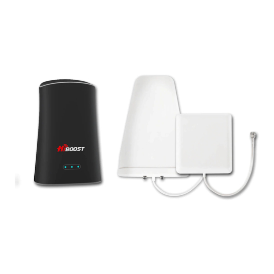
WHAT IS INCLUDED 1. HiBoost Mini 2. Outdoor Antenna & Cable 3. Indoor Antenna &Cable (option) 4. AC/DC Power Adapter 1 HOW IT WORKS The cellular booster provides reliable two-way cellular coverage by improving signal strength in homes, buildings, offices, and other areas where cellular reception is weak or unreliable. -
Page 4: How To Install Your New Cellular Booster
3 HOW TO INSTALL YOUR NEW CELLULAR BOOSTER Use the built –in antenna Use the indoor antenna 1.booster 2.outdoor antenna 3.cabel 4. power supply 5.indoor antenna 6. cabel (the same as No.3 cabel ) 3.1 Overview This guide will help you properly install your cellular booster kit. It is important to read through all of the installation steps before installing your equipment. - Page 5 • BOOSTER – select location •Install the booster in an area that is protected from the weather, properly ventilated and is away from excessive heat and moisture. • DONOR ANTENNA (OUTDOOR)- select location •Mount the signal (outdoor) antenna in an elevated outdoor location so that it points towards the cellular tower and away from where the inside antenna will be located.
-
Page 6: Plan The Layout Of Your System
3.2 Plan the layout of your system Before you get started you will need to plan the layout of your system. This involves checking signal strength for signals coming from the cellular tower, as well as antenna, booster and cable placement. 3.3 Check for Signal Strength Select a location on the roof of the building to install the signal antenna, by monitoring your cellular phone’s signal strength (signal bars) to find the strongest signal from your... -
Page 7: Install The Server (Indoor) Antenna
3.6 Install the Server (Indoor) antenna If you use the built-in antenna ,please ignore this step . Connect one end of the coaxial cable to the antenna and the other end to the cellular booster where it is marked “Indoor”. Select the installation location of your supplied server (indoor) antenna based on the following: Omni directional antenna... -
Page 8: Understand The Ports And Led Status,Mgc
4 UNDERSTAND THE PORTS and LED STATUS,MGC 4.1 Repeater ports Connector Description Indoor N-female connector,for connection to indoor antenna Outdoor N-female connector,for connection to outdoor antenna DC 12V Power wire port For debug connector 4.2 LED Status Status Definition Alarm green It is working properly Alarm... -
Page 9: Understand The Antenna
The panel is a directional antenna with a 120 degree reach and is designed to distribute the signal from a perimeter wall or ceiling. 5.3 Authorized Kitting Options The following accessories are authorized by the FCC to be used with the Hiboost Mini Signal Booster. Outdoor antenna & cable kit options Outdoor... -
Page 10: Troubleshooting
Outdoor Cable Outdoor Cable Outdoor Cable Loss Lower Upper Cellular AWS-1 700MHz 700MHz HiBoost200(50 1.25 1.25 feet) Indoor Antenna Indoor Antenna Indoor Antenna Gain Lower Upper Cellular AWS-1 700MHz 700MHz panel antenna Omni antenna Internal antenna Indoor Cable Indoor Cable Indoor Cable Loss Lower Upper... - Page 11 ¢The weak downlink signal leads to the low output signal level. Change thedirection or position of the outdoor antenna. You may also try replacing the outdoor antenna with a higher gain antenna to increase the incoming signal. *Check to see if it is necessary to add more indoor antennas. Barriers such as walls can block the signal indoors.
-
Page 12: Frequently Asked Questions
7 FREQUENTLY ASKED QUESTIONS WHY ARE THE LED LIGHTS TURNING FLASHING GREEN, FLASHING RED OR SHUTTING OFF? There are certain cases where your system could be experiencing oscillation. This can be attributed to either the quality of your input signal or having your outdoor antenna and indoor antenna too close together. - Page 13 Note:This equipment has been tested and found to comply with the limits for a Class B digital device, pursuant to Part 15 of the FCC Rules. These limits are designed to provide reasonable protection against harmful interference in a residential installation. This equipment generates, uses and can radiate radio frequency energy and, if not installed and used in accordance with the instructions, may cause harmful interference to radio communications.
- Page 14 IC RF EXPOSURE STATEMENT The device is compliance with RF exposure limits. The minimum distance from body to use the device is 20 CM. Le present appareil est conforme c山x conformite ou aux Ii mites d'intensite de champ RF. La distance minima le du corps a utiliser le dispositif est de 20 CM. SHENZHEN HUAPTEC CO., LTD 5th FL, E BLDG, Sogood Science Park, Hangkong Road, Xixiang, Bao'an, Shenzhen, China 518102...
Need help?
Do you have a question about the F08GI-5S-BTW and is the answer not in the manual?
Questions and answers